Rexroth 4WRPEH vs 4WRPH: Electronics, Signals and Replacement
For the legacy 2X versions examined here, 4WRPEH has on-board electronics, while 4WRPH uses an external amplifier. Both have spool-position feedback. Absence of E does not mean absence of feedback.
The references are RE29028/01.05 for 4WRPH6 and RE29037/10.05 for 4WRPEH10. The listed website products also differ in size, so electronics and mechanical compatibility must be assessed separately.
Where the spool-position controller sits
A suitable external amplifier drives the 4WRPH6 solenoid and receives its LVDT signal. It compares requested and actual spool position and regulates current. A normal supply connection alone cannot replace that controller.
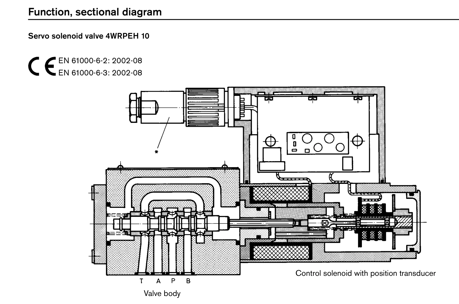
The 4WRPEH10 integrates this function in its OBE. The machine supplies power and a compatible command. The referenced catalog identifies A1 as ±10 V and F1 as 4–20 mA. Check the complete suffix.
| Item | Referenced 4WRPH6 2X | Referenced 4WRPEH10 2X |
|---|---|---|
| Spool feedback | Yes, with external amplifier | Yes, with OBE |
| Electronics | External | On the valve |
| Command | Match the amplifier | A1 ±10 V or F1 4–20 mA |
| Mechanical size | 6 | 10 |
| Flow reference | Selected spool at 70 bar | 50 or 100 L/min at 70 bar |
F1 centre command is not a pressure-valve zero command
Consider a hypothetical 4WRPEH10/F1 installation whose applicable bidirectional interface drawing places the midpoint at 12 mA. Programming 4 mA as zero, as for a unidirectional pressure request, does not request that midpoint and can produce directional movement.
The symptom can be normal supply and powered electronics, followed by movement to one side when automatic operation begins. Check interface, measured command and program scaling before changing mechanical null.
A1 and F1 are not interchangeable by changing the plug alone. Follow the specific power, signal-reference and shielding drawing. Neutral and de-energised behaviour also depend on the spool function.
Measure supply at the valve during the fault
RE29037/10.05 describes fast internal shutdown when the nominal 24 V supply falls below 18 V. A cabinet reading of 24 V can coexist with 17 V at the operating valve because of wiring or connection losses.
If an example fault coincides with 17 V at the valve and disappears after a connection repair restores supply, investigate the power path rather than replacing the valve. Qualified maintenance should measure the applicable points during the event. The 18 V condition belongs to this edition; other generations require their own data.
Size and spool still matter
The mounting patterns are ISO4401-03-02-0-94 for the referenced 4WRPH6 and ISO4401-05-04-0-94 for 4WRPEH10. Rewiring does not make these sizes mechanically interchangeable.
The website lists 30L and 40L 4WRPH6 configurations. The selected historical catalog does not list a standard 30L grade, so its characteristics must be obtained by the corresponding material number rather than copied from 40L. Assess the 4WRPEH10 50L configuration with its spool function and 70 bar reference condition as well.
What changes during machine commissioning?
On a 4WRPH6 installation, the external amplifier, coil and position sensor form the spool-control loop. Troubleshooting follows that chain. A command without matching coil current directs attention to amplifier output, enable conditions and coil continuity. Current with an abnormal position signal calls for sensor-supply, feedback-wiring and valve-response checks.
4WRPEH10 places the spool-control electronics on the valve. External checks focus on valve-terminal supply, command and applicable monitoring signals. A same-configuration replacement avoids separately connecting an external spool-control amplifier, but the machine's speed, position or pressure control must still be verified.
For example, if a press slide repeatedly corrects near its target, compare spool monitoring with slide-position feedback. A spool that follows command while the slide lags points towards further checks of the cylinder, piping, load and machine control settings. More aggressive spool-loop adjustment may not resolve the slide behaviour.
Mapping an F1 command to two directions
For the referenced F1 interface, 12 mA is the command midpoint. The 4–12 mA and 12–20 mA ranges command opposite directions. The applicable spool symbol and connection diagram establish which work port corresponds to each direction.
Suppose software maps 4–20 mA as a unidirectional 0–100% output. At a displayed 0%, it sends 4 mA, which is a directional end command. If the machine needs the midpoint command at rest, map the stop value and both directions around 12 mA.
Qualified personnel should then verify positive, negative and midpoint responses under permitted machine conditions, including feedback direction. A 12 mA midpoint command does not itself establish load holding; spool function and the complete circuit determine that behaviour.
Convert NG6 and NG10 flow grades into cylinder speed
Consider the catalogue's 24 L/min 4WRPH6 grade and 50 L/min 4WRPEH10 grade at the same 70 bar total rated valve drop. With a 50 cm² effective cylinder area, these flows correspond to theoretical speeds of 80 and approximately 167 mm/s.
A 100 mm/s requirement needs 30 L/min. The 24 L/min grade is insufficient at that rated condition; the 50 L/min grade has flow margin. Actual valve differential, pump delivery and load still govern selection. This difference comes from size and flow grade rather than the presence of OBE.
The website's 4WRPH6 30L configuration is absent from the referenced historical standard-grade table. Obtain its own data rather than substituting the 24L or 40L figures.
Establish on-board versus external control, then match A1/F1, valve-side supply, feedback and size. The E changes the electronics arrangement; sizes 6 and 10 change the mounting. Both need an explicit compatibility check.