Rexroth 4WRPEH: Matching A1 and F1 Signal Interfaces
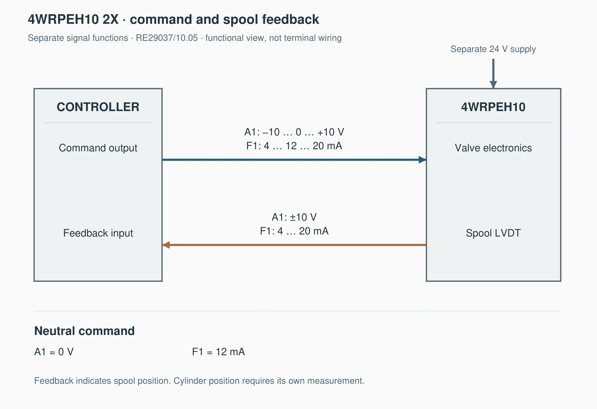
A1 and F1 are different interfaces. A1 accepts a voltage command; F1 accepts a current command. For the bidirectional version discussed here, neutral is 0 V or 12 mA respectively. A matching plug and correct 24 V supply do not establish a compatible command interface.
This article is limited to 4WRPEH10 component series 2X, using RE29037/10.05. Terminal functions, feedback formats and low-current behaviour must not be transferred unverified to other sizes or later generations.
Establish neutral before scaling percentages
A1 uses −10 to +10 V with 0 V neutral. F1 uses 4–20 mA with 12 mA neutral: 12–20 mA commands one direction and 4–12 mA the other. Actual positive machine motion also depends on the spool arrangement and piping.
Treating F1 as a unidirectional 4 mA zero-speed to 20 mA full-speed interface misplaces neutral. At 4 mA, it is already at one directional command endpoint.
| Normalised bidirectional command | A1 voltage | F1 current |
|---|---|---|
| −100% | −10 V | 4 mA |
| −50% | −5 V | 8 mA |
| 0% | 0 V | 12 mA |
| +50% | +5 V | 16 mA |
| +100% | +10 V | 20 mA |
These percentages describe command position, not guaranteed cylinder-speed percentages. Metering characteristics, differential pressure and cylinder areas still affect motion.
Centre the PLC conversion on bidirectional neutral
Assume a signed internal command from −100 to +100%. A1 conversion is U = 0.1 × command percentage. F1 conversion is I = 12 + 0.08 × command percentage. The resulting units are volts and milliamperes.
For +25%, the corresponding values are +2.5 V and 14 mA; for −25%, −2.5 V and 10 mA. Establish neutral and endpoints before checking direction and limits.
The analogue module's raw integer range depends on its type and selected range. Program integers, physical voltage and physical current must be checked separately. One module's full-scale integer is not a universal PLC convention.
An identical connector does not establish interchangeability
The cited A1 has a differential voltage input with 100 kΩ input resistance. F1 has a 200 Ω input burden. Select the appropriate PLC voltage or current output and check current-loop drive capability and wiring.
At 20 mA, the 200 Ω F1 input produces a 4 V drop. That is only part of the loop voltage budget; wiring and other series loads also matter. It does not make a conventional voltage output equivalent to a current output.
Changing between A1 and F1 generally involves the controller range, program conversion, wiring and feedback input. Reusing the old plug alone does not complete the replacement.
Keep command and spool feedback separate
In this catalog, A1 provides a ±10 V spool-position test signal and F1 provides 4–20 mA spool-position feedback. These represent the LVDT-related spool position, not cylinder position or measured flow.
A +50% command with corresponding spool feedback supports a conclusion about spool following. Cylinder speed may still fall because of supply or load conditions, and cylinder position requires its own measurement.
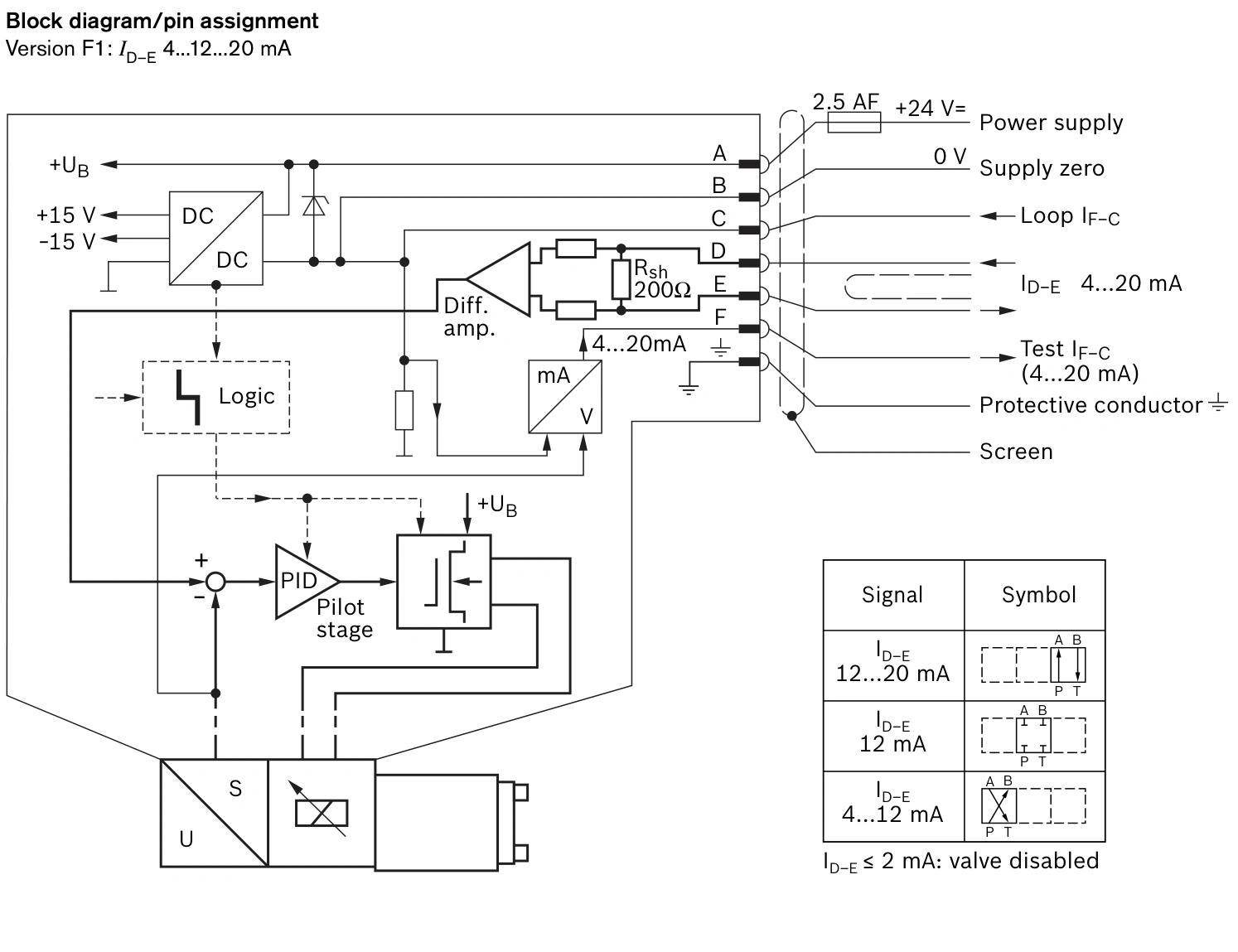
The catalog distinguishes supply zero and feedback reference zero. Its A1 drawing explicitly instructs that reference C must not be connected to supply zero. Follow the actual version's wiring documentation rather than combining connections because both are described as zero.
Zero current and 12 mA are different states
Normal F1 neutral is 12 mA. The cited 2005 document also specifies valve disabling at input current of 2 mA or less, distinguishing a lost-current state from normal neutral. Do not use 0 mA as the ordinary zero-speed command or treat this product behaviour as a complete machine safety-stop circuit.
Include analogue-output behaviour during controller startup, power loss and communication faults in commissioning. Correct neutral after program startup does not exclude an inappropriate temporary output beforehand.
Check four groups of values during replacement
Check the actual A1/F1 and supply configuration; the PLC channel's physical range; measured negative endpoint, neutral and positive endpoint outputs; and spool feedback together with machine direction.
In the approved commissioning state, verify small commands in both directions before checking output limits and response. Qualified personnel should perform electrical measurement and wiring changes with existing interlocks retained. Repeated full-scale commands are not a method for finding neutral.
Match signal type, neutral and feedback together. A1 centres on 0 V; this F1 version centres on 12 mA. Once conversion and wiring are correct, verify spool response and cylinder motion separately.