Rexroth 4WRZE: Power and Command Present, but No Movement
The 4WRZE is pilot operated. Its pilot stage establishes a pressure differential that moves the main spool. Powered electronics and an existing PLC command do not by themselves establish that hydraulic condition.
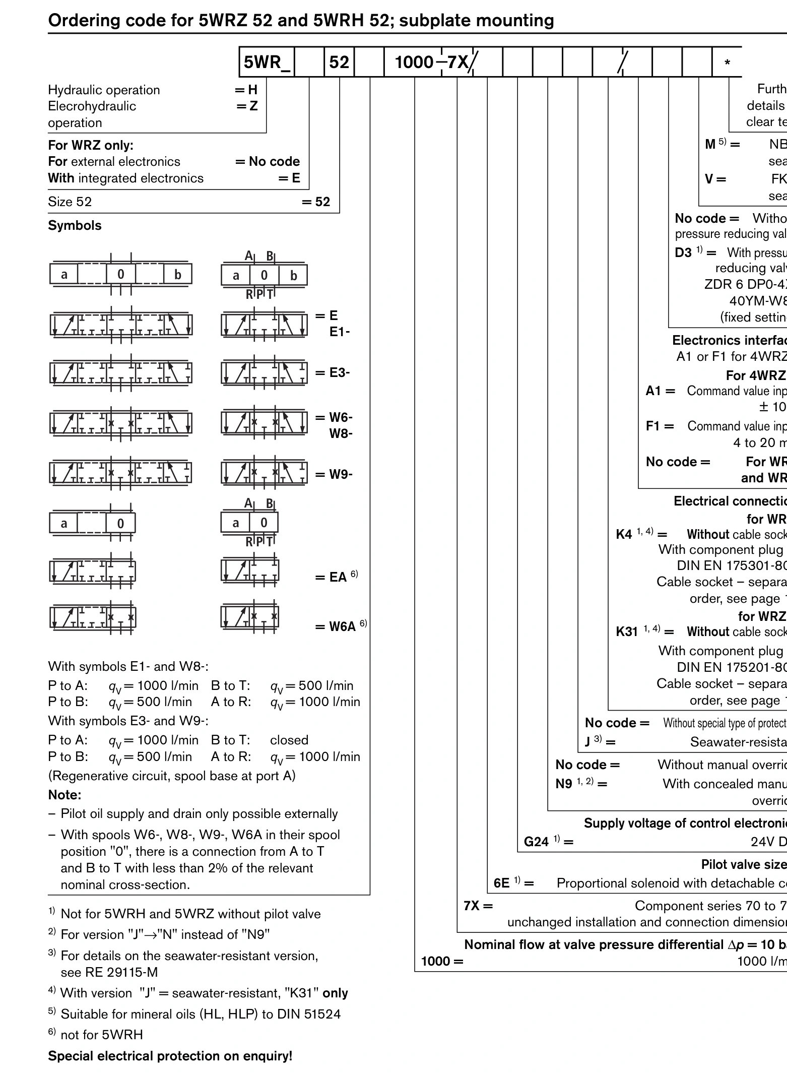
This article concerns the listed 4WRZE10…7X family and the routing choices documented in RE29115/10.05. Check the actual E pilot-routing and D3 configuration against its drawing rather than importing another generation's requirements.
Establish pilot supply and return routing first
The ordering table defines four arrangements.
| Routing code | Pilot supply | Pilot return |
|---|---|---|
| No code | External X | External Y |
| E | Internal main supply | External Y |
| T | External X | Internal return |
| ET | Internal main supply | Internal return |
These determine the relevant measuring points and subplate passages. Missing X supply on an external-supply version, or an obstructed Y passage on an external-drain version, can prevent movement despite a command. Main P pressure does not establish adequate pilot conditions.
Case 1: Main pressure is present, external pilot supply is absent
Assume an external-supply version has 120 bar at P but nearly zero at X, with correct power and command. Investigate the pilot source, isolation state and X passage first. Pressure at P does not automatically appear at a separately supplied X connection.
Restoring specified pilot supply and recovering movement at the same command supports that diagnosis. This reasoning depends on confirming external supply first.
Case 2: Pilot inlet pressure exists, but drain pressure is too high
Assume a particular circuit requires at least 10 bar effective pilot differential. An inlet reading of 20 bar and return reading of 18 bar provide only 2 bar. A positive inlet-gauge reading therefore does not satisfy that circuit.
Check Y routing, shared-return backpressure and subplate passages. The 10 bar value is an example requirement, not a universal minimum for every 4WRZE size and operating condition.
The symptoms may be slow or incomplete opening, or changing response as return pressure varies. Restore return conditions and repeat the original command rather than immediately increasing output.
Case 3: Internal pilot supply changes with P pressure
E and ET versions obtain pilot oil internally. If the main circuit unloads during one phase, the required pilot differential may disappear too. Movement may work under load but fail during the unloaded phase.
Review the pilot design against that operating step. D3 identifies the catalog's pressure-reducing arrangement; it cannot generate pilot pressure without a source.
With pilot conditions established, examine the main stage and load
Once qualified maintenance has established power, command and pilot conditions, compare work-port pressure with actuator response. Rising work-port pressure without movement directs attention to load, return and holding devices. Adequate pilot action without corresponding main-stage response calls for the prescribed valve tests.
Operators can record operating phase, existing gauges, command and alarms. Pressurised measurements, subplate checks and internal work require qualified personnel. Do not improvise by forcing overrides, increasing pressure or blocking ports.
If the fault starts after replacement, compare pilot arrangements first
Suppose the original valve used internal pilot supply and its manifold only provided the main flow connections. Replacing it with an external-pilot configuration without a separate X supply leaves normal pump pressure and electrical command but no required pilot source.
An external Y drain that does not match the manifold can likewise prevent correct pilot operation. Compare old and new model codes, hydraulic symbols and manifold passages. Qualified maintenance personnel should resolve the configuration differences under the applicable procedure.
When the old valve operated but both directions fail immediately after replacement, this comparison is more relevant than starting with PLC tuning.
Record pressure during the actual motion
Pilot pressure can appear normal at rest yet fall during motion. Drain pressure may rise at the same time. Readings taken only while stopped or unloaded can miss the condition preventing main-spool operation.
For example, several circuits may share a pilot supply. If 4WRZE slows when another mechanism operates and recovers when it stops, compare pilot supply and return pressures during separate and simultaneous operation. Investigate source capacity, restrictions and shared-branch demand.
If the fault instead coincides with another mechanism discharging oil, compare Y pressure or the relevant internal return pressure. Supply loss and return backpressure can both reduce effective pilot differential, but require checks at different points.
Work-port pressures help locate downstream problems
Once power, command and pilot conditions meet requirements, compare A and B pressures with actuator pressures. Rising work-port pressure without cylinder movement calls for checks of load, mechanical obstruction and downstream load-holding valves.
If work-port pressure does not build, compare P pressure during motion, main-stage response and downstream leakage paths. This observation alone cannot separate a closed spool, inadequate supply and downstream loss.
| Observation | Next comparison | Investigation |
|---|---|---|
| Neither direction works after replacement | Old/new pilot codes and manifold passages | Missing X supply, obstructed Y drain or configuration mismatch |
| Works loaded but fails while unloaded | P and pilot pressures across the operating step | Internal pilot source losing pressure during unloading |
| Slows during simultaneous machine actions | Pilot supply and return during both duties | Shared supply capacity or return backpressure |
| Work-port pressure rises but mechanism stays still | Actuator pressure, load and holding devices | Downstream circuit or mechanical resistance |
Time-aligned records of operating step, command and pressures are more useful than unrelated gauge photographs. Operators can record when the fault occurs; qualified personnel should perform any additional pressurised measurements.
Identify where pilot oil comes from and where it returns, then check effective differential during the failed movement. Main pressure does not replace pilot conditions. Investigate the main valve and load after those conditions are established.