Rexroth 4WRP: Flow, Spool and Drive Configuration
The 4WRP10W63S-1X/G24Z4/M is a directly operated proportional directional valve with spool-position feedback and external control electronics. Its 63 L/min rating is specified at a total valve pressure differential of 10 bar. S identifies a progressive flow characteristic. Both details affect the speed available on the machine.
This article uses the 4WRP component series 1X catalog RE29022/01.05. Similar-looking model names can use different electronics and connections; an integrated-electronics wiring arrangement must not be transferred to this version.
Put the 63 L/min rating into the circuit pressure budget
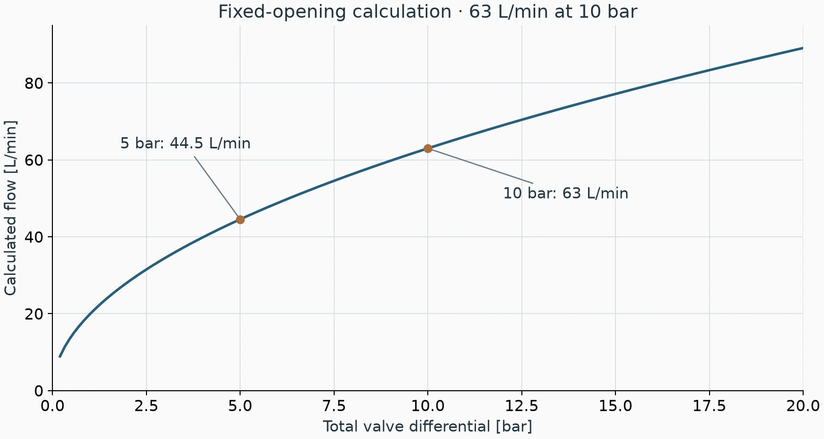
The catalog rates flow at 5 bar per metering edge, or 10 bar across the two active edges. The rating applies to a defined opening and differential. Installed flow depends on the differential actually available across the valve.
Assume a cylinder effective area of 100 cm² and a required speed of 100 mm/s. The theoretical supply requirement is 60 L/min. At rated conditions, the 63 L/min version provides only 3 L/min above that target. Pump delivery, actuator leakage and actual circuit losses still require checking.
Using the square-root orifice relationship at the same opening, reducing total valve differential from 10 to 5 bar gives approximately 63 × √(5/10) = 44.5 L/min. The assumed cylinder would travel at about 74.2 mm/s, appreciably below the 100 mm/s target.
This comparison assumes that the active metering edges can be represented by the same-opening approximation. Differential-cylinder area ratios, spool passages and actual pressure distribution require the relevant OEM characteristics and circuit calculation.
Progressive metering gives a different low-speed command response
The S configuration has a progressive characteristic. Command and flow do not follow one straight line throughout the range. Under comparable conditions, the lower-opening region gives a gentler flow increase; the flow increase becomes steeper as opening grows.
A press requiring a slow approach and a rapid return therefore needs a command established for each motion. A command voltage proportional to the ratio of those speeds is insufficient, especially when travel direction and effective cylinder area also change.
Equal command increments based on experience with a linear valve can produce small speed changes initially and larger changes later. Establish a command-versus-speed record at stable oil temperature and a repeatable load before adjusting the process stages.
Positive overlap affects motion near neutral
This 4WRP generation uses positive overlap. From neutral, the spool first travels through the overlap before opening the working passages. A small command change may therefore produce no visible cylinder motion.
If a feeder remains stationary over a small command interval and then starts, separate metering overlap, load friction and amplifier adjustment. A large compensation intended to jump across the interval can deliver excessive flow once motion begins.
During authorised commissioning, record the start-of-motion command in both directions and the speed increase immediately afterwards. Apply the OEM amplifier procedure. This behaviour alone does not establish spool sticking or a damaged valve.
| Configuration or condition | Possible machine behaviour | Compare |
|---|---|---|
| 63 L/min rating with inadequate differential | Target speed unavailable at high load | Valve pressures and pump delivery |
| S progressive characteristic | Equal commands give unequal speed increments | Command-versus-speed record |
| Positive overlap combined with friction | No motion at small command, then a start | Both starting commands, ramp and amplifier settings |
| Mismatched electronics or feedback | Abnormal spool response to command | Valve/electronics compatibility |
G24 does not make the PLC a coil amplifier
This model uses external electronics. In its ordering table, G24 denotes the +24 V DC supply for those electronics. Coil drive and AC/AC position feedback require the appropriate control circuitry. The PLC analogue command belongs at the input of a compatible control unit.
The catalog lists VT-VRPA2-537 arrangements for NG10. After replacing a valve or amplifier, check the applicable connection, matching and adjustment instructions. A connector that fits does not establish electrical compatibility.
When the command appears normal but motion is wrong, distinguish controller output, amplifier supply, coil drive and position feedback. A displayed 50% command establishes the requested target, not the actual spool position.
The NG10 L drain has its own limit
The mounting interface of this 4WRP10 includes an additional L drain. The section drawing specifies a maximum L-port pressure of 2 bar. Its limit is separate from the T-port rating; a higher permissible T pressure does not permit routing L into a high-backpressure return.
If behaviour deteriorates after moving the valve to another manifold, inspect the L passage before continuing to alter electrical gains. Check the mounting drawing, seals, blocked passages and any shared-return backpressure.
E, W, E1 and W1 also identify different passage arrangements. The E1/W1 flow allocation shown in the catalog does not automatically apply to a plain W spool. Maintain the required spool symbol and interface when replacing a valve.
Select the 4WRP by its rated flow conditions, progressive metering, positive overlap, external electronics and L-drain requirements together. The pressure and flow budget determines achievable speed; correct electrical and drain connections allow the valve to perform as intended.