MOOG Servo Valves: Cylinder Drift at Zero Command
A cylinder moving slowly after a zero-speed command does not by itself establish internal leakage. Electrical bias, hydraulic null, load-driven leakage and cylinder sealing can all influence the stopped condition. Establish where zero is being measured, then compare movement with load.
MOOG valve architectures differ. The G761 uses mechanical feedback; applicable D661 versions use main-spool position feedback and electronics. This discussion uses the 761 catalog Rev M, April 2024, and the relevant installation literature. It does not prescribe one null-adjustment procedure for every series.
A fixed position target does not require zero valve output
A position controller may apply a small continuous correction to hold the cylinder against load, hydraulic-null offset or leakage. A stationary target on the screen and a zero electrical command at the valve are different conditions.
For example, a 100 mm target, actual position close to 100 mm and a small steady control output may indicate active closed-loop compensation. Forcing that output to zero could remove the correction holding the position.
Conversely, a zero-speed display with an unexpected output offset can involve programmed compensation, analogue-output error or reference-potential problems. Check the actual signal according to the valve interface, rather than relying on the screen value.
Electrical zero and hydraulic null are separate
Hydraulic null affects flow and pressure distribution around the valve's neutral command. The 761 catalog shows standard, underlapped and overlapped null-cut options. Their near-null flow gains differ; one ideal straight line does not represent every configuration.
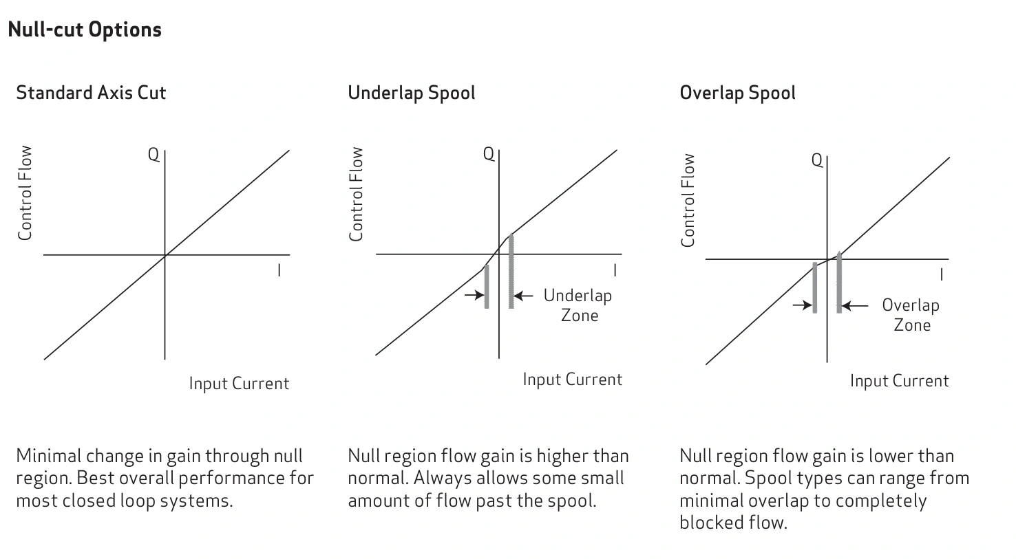
If the signal is at its specified neutral but a small repeatable opposite correction is needed to stop the cylinder, the system has a compensable holding offset. That observation alone does not assign the entire offset to the valve. Compare load and temperature next.
OEM null adjustment is a calibration procedure for the applicable product. Turning an adjuster to cancel drift under one load can hide a leakage or signal problem. Preserve the original signal, movement and pressure records before qualified personnel follow the correct manual.
A 15 mm movement in 30 seconds represents what flow?
Assume an effective working area of 50 cm². Moving 15 mm in 30 seconds gives an average speed of 0.5 mm/s. The corresponding effective flow is approximately 50 × 0.5 × 0.006 = 0.15 L/min, or 150 cm³/min.
This quantifies movement, but it is not automatically 150 cm³/min of valve leakage. Valve metering, cylinder internal leakage and connected branches can all participate in the oil balance.
In a single-rod cylinder, chamber volume changes are unequal. Internal piston leakage changes the pressure balance, but sustained movement also depends on external replenishment, discharge paths and pressure conditions. A leaking piston seal alone is not a complete explanation for every drifting cylinder.
Load-sensitive drift directs attention to hydraulic paths
Assume repeatable movement of 3 mm in 30 seconds unloaded and 15 mm loaded, at the same oil temperature and measured neutral signal. Drift changing with the load-related differential makes leakage and load-dependent hydraulic paths a priority.
If drift reverses with load direction, pressure-driven leakage or load-holding behaviour deserves further investigation. This still does not separate the valve, cylinder and other connected branches without a correctly defined isolation test.
If drift remains in one direction under light and heavy loads and a small fixed opposite correction repeatedly stops it, inspect electrical bias and hydraulic null first. These patterns prioritise checks; they are not final component-failure diagnoses.
| Comparison | Observation | Check first |
|---|---|---|
| Fixed target, nonzero actual output | Continuous closed-loop correction | Error, compensation logic and output measurement |
| Stable neutral, repeatable small cancelling correction | Consistent holding offset | Electrical zero and hydraulic null |
| Larger load produces greater drift | Movement depends on differential | Valve, cylinder and branch leakage paths |
| More drift at operating temperature | Temperature-related behaviour | Repeatable measurements at defined temperatures |
| Motion starts and stops or oscillates | Possible closed-loop correction cycle | Position error and output over time |
Increased hot drift does not identify wear by itself
Temperature affects viscosity and clearance leakage, but can also affect electrical offset, sensor drift and seal friction. A stronger hot symptom establishes temperature dependence, not a unique cause.
At the same stopping position and similar load, compare actual neutral signal, both chamber pressures and 30-second movement cold and at normal temperature. A changing signal directs attention to control. An unchanged signal with increased load-sensitive drift justifies further hydraulic testing.
Useful records do not require opening a line
Use the existing position display and a repeatable starting point. Record position and pressure at 10, 20 and 30 seconds. Where appropriate, a fixed scale can support safe observation from outside the moving-load area.
Several consistent records are more useful than one impression that the cylinder seems to move. If instrument resolution is inadequate, record direction and cycle behaviour without presenting an estimate as a precise leakage measurement.
Confirm actual command, quantify movement, then compare load and temperature. A stable compensable offset points first toward zero calibration; drift strongly affected by differential points toward leakage and holding paths. Component replacement should follow the relevant isolation-test evidence.