How to Verify MOOG Servo Valve Performance After Repair
Post-repair acceptance records can be organized around five topics: test conditions, null and small-signal response, bidirectional sweeps and repeatability, flow and leakage, and dynamic performance with acceptance conclusions. The numbering organizes the review; it is not a universal MOOG test sequence.
Keep a record for each applicable topic and compare the results with the requirements for the actual valve configuration. This shows what has improved and which items still need attention.
1. Confirm the configuration and align test conditions
Record the complete model designation and ordering configuration, including the spool, signals, pilot connections and fail-safe functions. Use the matching documentation to establish test modes, items and limits for the before-and-after comparison.
Record supply pressure, valve pressure drop, pilot and return conditions, oil temperature, viscosity, sweep rate and signal ranges for both tests. For pressure-control applications, also record the load, entrapped fluid volume and controller settings.
Keep chart scales, sampling and filtering consistent. Null records establish the sweep reference state. Perform external leakage and basic function checks during pressurization as specified by the test stand procedure. Actual test order, repeat checks and operating conditions follow the applicable valve documentation and stand procedure.
2. Check null stability and small-signal response
Confirm the input reference and feedback center value for the selected configuration. Record output deviation at the specified zero command and the input bias required to achieve hydraulic null. Where applicable, assess null shift at normal oil temperature and different pressures.
After null adjustment, check whether it remains stable. If deviation increases after warm-up or null changes after a sweep, investigate temperature effects, signal references and valve condition.
Small-signal response near center also matters. Continuous adjustment and low-speed motion require stable responses to small command changes. Full-stroke operation alone does not establish performance in the fine-control range.
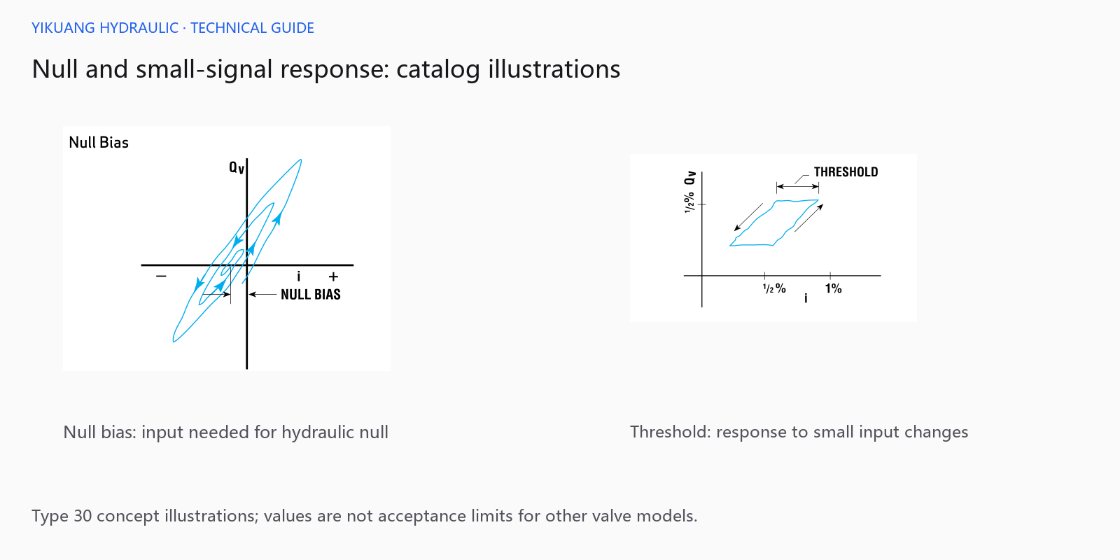
Perform threshold or resolution testing using the specified method, recording input increments and the resulting output changes. Full-range bidirectional sweeps help assess direction-dependent behavior. Recheck null after warm-up or sweeping as required by the procedure.
3. Compare bidirectional sweeps and repeatability
Slowly increase and decrease the input over the prescribed range and compare the resulting curves. Hysteresis can be evaluated as the difference in input required to produce the same output. Point selection and normalization follow the applicable test method.
Before calculating, confirm that both traces represent the same measured quantity and use consistent ranges. The distance between different channels on a dual-axis chart cannot directly be treated as a hysteresis percentage.
Repeat sweeps under the same conditions to assess whether results reproduce consistently. A smaller bidirectional difference accompanied by substantial variation between repeated sweeps still requires further evaluation.
Keep the bidirectional and repeated-sweep records. Flow and leakage measurements complement these results when assessing hydraulic performance against the model requirements.
4. Measure flow at the specified pressure drop and check leakage
Measure rated flow at the applicable pressure drop. Supply pressure also has to overcome load and return pressure, so record the actual valve pressure drop to support comparison with the flow rating.
Leakage items depend on construction and configuration. Record external leakage, main-stage internal leakage or pilot consumption separately where applicable. State test pressure, oil temperature, port conditions and the measurement boundaries.
Evaluate internal leakage near null against the limits for the actual model. Different spool configurations and pilot designs have different requirements; values from another series should not be substituted.
Static tests assess null, the input-output relationship, flow and leakage. Dynamic tests assess whether the valve responds as required to rapidly changing commands.
5. Review dynamic performance and acceptance conclusions
Step tests examine response buildup, overshoot and settling. Frequency response tests examine amplitude attenuation and phase lag at the specified command amplitude. Select the applicable tests for the machine requirements and retain their conditions.
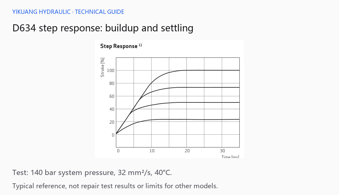
D634 series — context for this example
For PQ valves with pressure control, pressure response also depends on load, fluid volume and controller settings. Use the applicable operating mode and record fluctuations and settling after pressure buildup.
Combine the applicable static and dynamic results in one acceptance report. List the measured value, requirement and conclusion for each item. If testing covered only static performance, identify the dynamic items that remain unverified.
| Review topic | Records to retain | Evaluation basis |
|---|---|---|
| 1. Consistent conditions | Configuration, operating conditions, signals and sampling settings | Applicable documentation and test procedure |
| 2. Null and small signals | Input bias, output, temperature effects and small-signal response | Configuration-specific null and threshold requirements |
| 3. Bidirectional and repeated sweeps | Hysteresis calculations and repeated results | Specified methods and limits |
| 4. Flow and leakage | Flow, pressure drop, leakage and port conditions | Model-specific conditions and limits |
| 5. Dynamics and machine verification | Response data, test scope and actual control behavior | Valve and machine acceptance requirements |
Distinguish items that meet requirements, have improved but remain outside limits, or have not been verified. After stand acceptance, personnel experienced in electrohydraulic controls should carry out controlled commissioning under the machine procedure, confirming signal direction, interlocks, load control and actual motion.
For a repair assessment, provide the complete nameplate, fault symptoms, pre-repair records and machine requirements. For reading the curves, see MOOG Servo Valve Flow and Frequency Response.