Servo vs Proportional Valves: Bosch Rexroth 4WREE and MOOG D633 Compared
Servo and proportional valves often appear on the same selection shortlist. The useful comparison is how each valve is driven, how it uses feedback, where it can regulate reliably and whether those characteristics suit the machine.
This article compares the Bosch Rexroth 4WREE 6-3X with the MOOG D633. Both are NG6, direct-operated valves with spool position feedback and integrated electronics. Their shared features provide a useful basis for discussing the two product categories without mixing valve sizes or numbers of drive stages.
MOOG D633 series and published models
Proportional valves can have closed-loop spool control
Rexroth defines the 4WREE as a direct-operated proportional directional valve with electrical position feedback and integrated electronics. The D633 is a direct-drive servo valve with integrated electronics and an analog interface.
Rexroth brand directory (4WREE is not currently listed)
The 4WREE product image below shows the valve and its integrated electronics housing. Spool feedback comes from the specified configuration, rather than its external appearance.
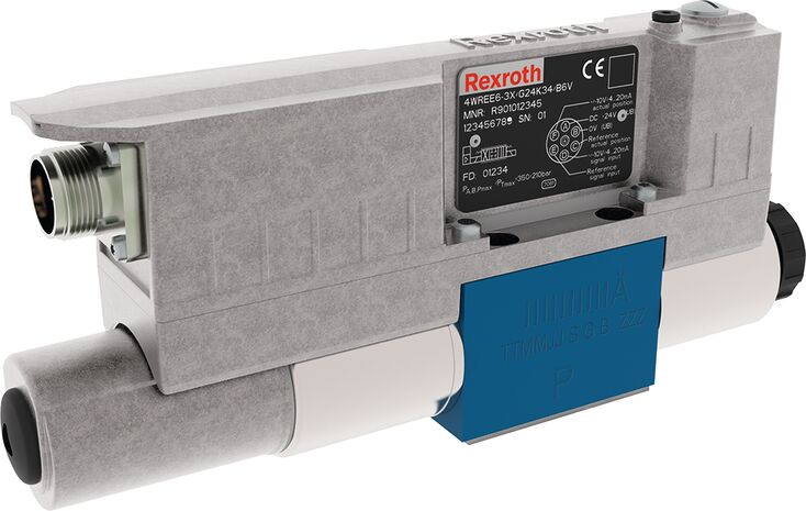
Spool feedback is therefore available in both product categories. Describing this pair as a feedback-equipped servo valve versus a proportional valve without feedback would misrepresent the 4WREE configuration.
The internal position loop controls the spool. A machine needs the relevant position, speed or pressure sensor to close an external loop around its actual process. Cylinder speed can still change with available pressure drop and load even when spool tracking is correct.
| Item | Bosch Rexroth 4WREE 6-3X | MOOG D633 |
|---|---|---|
| Official product category | Proportional directional valve | Direct-drive servo valve |
| Size | NG6 | NG6 / ISO 4401 Size 03 |
| Operation | Direct-operated | Permanent-magnet linear force motor drives the spool directly |
| Spool feedback | Electrical position feedback | Closed-loop spool position control |
| Electronics | Integrated OBE | Integrated electronics, analog interface |
| Standard rated flows | 4, 8, 16 and 32 L/min | 5, 10, 20 and 40 L/min |
| Conditions for these ratings | 5 bar per spool land (10 bar total for a typical four-way path) | 35 bar pressure drop per spool land |
The flow conditions differ, so the numbers cannot be used for a direct capacity ranking. Check spool, electrical and installation configurations against the complete ordering code.
Servo valves can also be direct-driven
The D633 permanent-magnet linear force motor moves the spool directly and applies force in both directions. No pilot supply is needed to drive the spool. Servo valves are therefore not limited to two-stage pilot-operated designs.
Drive construction affects supply, electrical and dynamic requirements, but it is only one selection factor. Review the complete flow, spool and electronics configuration rather than inferring internal construction from the product category.
Both valves in this comparison are direct-operated. The relevant questions concern their control range, spool characteristics, dynamic behavior and application requirements, rather than simply whether they need pilot oil.
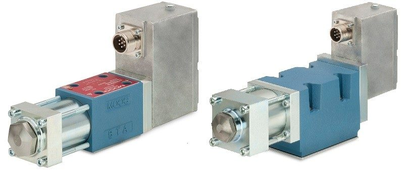
The following image shows the D633/D634 family discussed on the MOOG product page. For this comparison, the D633 specifications remain the relevant reference.
Establish the pressure-drop definition before comparing flow
The official 4WREE 6-3X selection information lists 4, 8, 16 and 32 L/min at 5 bar per spool land on the Chinese selection page, corresponding to 10 bar total for a typical four-way path. The D633 standard ratings are 5, 10, 20 and 40 L/min at 35 bar per spool land.
Comparing 32 L/min directly with 40 L/min would overlook the test pressure drop. Establish whether each rating refers to the total valve, one metering edge or a specified flow path before assessing both valves at a common operating condition.
For sharp-edged metering orifices at a fixed opening, flow approximately follows the square root of pressure drop. A rating given at a higher pressure drop does not establish the same flow at a lower one. Operating limits and permissible pressure drops also need checking.
I would calculate the flow required at the target cylinder speed first, then estimate load pressure and line losses. Knowing the pressure drop actually available across the valve gives the comparison a practical basis.
For small corrections, examine threshold, hysteresis and center characteristics
Slow speed control and small position corrections often use the region near spool center. Small command changes need to produce repeatable responses, and direction reversals may require different inputs for the same output.
Threshold, hysteresis, null shift and spool overlap help assess this behavior. Spool configurations can have different center flow paths and flow characteristics. Their actual curves are more informative than the proportional or servo label.
For operation mainly at larger openings, flow capacity and load may be more prominent. For small, rapid corrections, static and dynamic behavior near center deserves closer attention.
Read dynamic curves at the relevant command amplitude
A single step response time does not describe every movement. Large opening changes and small periodic corrections impose different motion requirements. Read frequency response at a command amplitude close to the application.
The D633 catalog provides dynamic curves at different amplitudes. When comparing the selected 4WREE configuration, check test pressure, oil temperature, viscosity, stroke and the response definition. Retain any differences in conditions rather than forcing a performance ranking.
The machine loop also includes piping, load, sensors and the controller. Valve dynamics support selection, while the final motion still requires verification in the actual circuit.
Rapid travel and fine adjustment impose different requirements
Assume a cylinder has an effective area of 20 cm² and needs a rapid travel speed of 0.25 m/s. The required flow is 30 L/min. Check whether the valve can provide it at the actual available pressure drop, then assess the response required for that movement.
If the same cylinder also needs to move at 0.005 m/s, the required flow is only 0.6 L/min. A valve sized for rapid travel may use a very small part of its opening range at low speed. Small-signal response and flow characteristics near center then become important.
This is a calculation example for the selected effective chamber, neglecting leakage. It illustrates how one machine can require both high flow and fine control. Meeting the maximum flow requirement still leaves the question of reliable regulation near 0.6 L/min.
The chart puts those two requirements side by side. The wide flow range explains why maximum flow and fine regulation need separate checks.
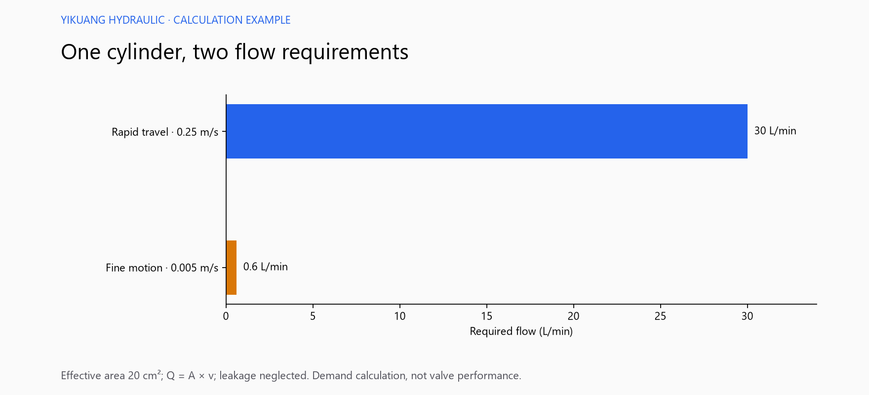
For both the 4WREE 6-3X and D633, assess these operating points against the curves for the actual configuration. At low speed, examine threshold, hysteresis and overlap; during rapid travel, examine available flow and dynamics. Position holding also requires a separate assessment of load and circuit leakage.
If the machine mainly makes small periodic corrections, review frequency response at the actual command amplitude. Tracking capability can vary with amplitude within one series, so a single step response time cannot replace that comparison.
Finally, check control interfaces and installation requirements. Although both valves are NG6, ports, spool center condition, pin assignments, feedback ranges, enable functions and electrical supply capacity must match the application. Suitable performance does not establish direct interchangeability.
For the effects of machine conditions on control performance, see Why a Servo Valve Can Pass Bench Testing but Perform Poorly on the Machine.