MOOG D633 vs D634: Differences and Valve Selection
The D633 and D634 are direct-drive servo valves. A permanent-magnet linear force motor drives the spool directly, with an integrated amplifier and spool position feedback. Their main differences are flow capacity and mounting size. The D633 offers rated flows of 5, 10, 20 and 40 L/min; the D634 offers 60 and 100 L/min.
The D633 covers smaller-flow duties. The D634 serves applications needing more flow for faster motion. Cylinder flow demand alone does not settle the choice: as the load increases, less pressure drop remains across the valve, reducing the flow available from the same opening.
This comparison covers the D633-R and D634-R using Moog's November 2024 Rev. D catalog.
Main differences
| Item | D633 | D634 |
|---|---|---|
| Mounting size | Size 03, commonly NG6 | Size 05, commonly NG10 |
| Mounting interface | ISO 4401-03-03-0-05 | ISO 4401-05-05-0-05 |
| Rated flow | 5, 10, 20, 40 L/min | 60, 100 L/min |
| Rated-flow pressure drop | 35 bar per metering edge | 35 bar per metering edge |
| Series maximum flow | 75 L/min | 180 L/min |
| Maximum operating pressure at P, A and B | 350 bar | 350 bar |
| 0–100% spool-stroke step response | ≤12 ms | ≤20 ms |
| Weight | 2.5 kg | 7.9 kg |
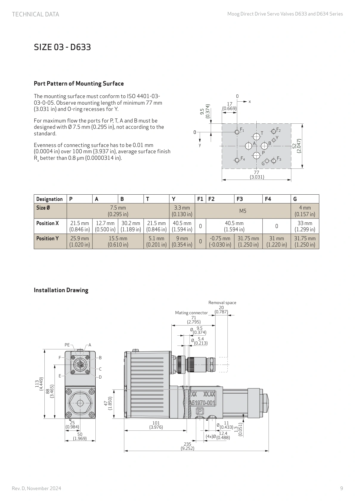
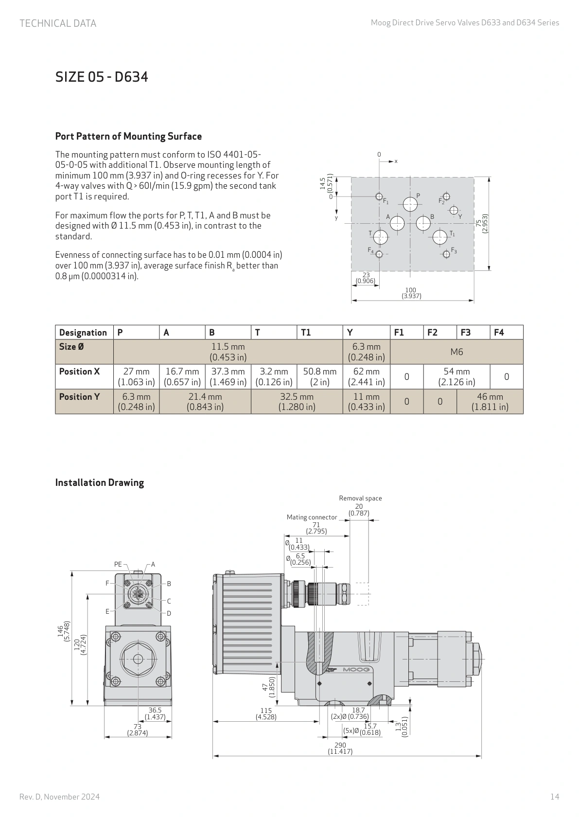
The D634 has a larger body as well as greater flow capacity. It does not fit directly onto a D633 manifold. The mounting face, port positions and installation space differ, so replacement usually involves manifold changes.
The 75 and 180 L/min figures are series maximum flows, rather than flow available under every operating condition. Once a rated-flow option is chosen, its flow under load still needs to be calculated.
The D633 has the shorter catalog step-response figure. Both figures were measured at 140 bar system pressure, 40 °C oil temperature and 32 mm²/s viscosity. They describe spool travel time. Cylinder positioning time also depends on the load, pipework and controller settings.
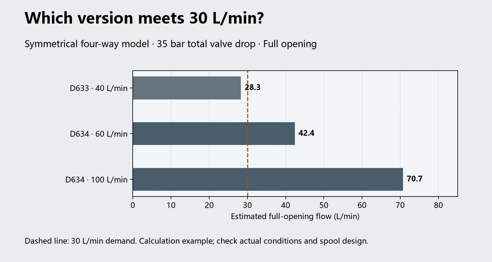
Will a 40 L/min D633 supply a cylinder needing 30 L/min?
Consider a cylinder with an effective area of 20 cm² in the direction being calculated and a required speed of 0.25 m/s. Its supply flow demand is:
Q = A × v = 30 L/min.
A 40 L/min D633 appears large enough. However, that rating assumes a pressure drop of 35 bar per metering edge. For symmetrical four-way operation, the supply and return metering edges together require 70 bar.
If the load is high and only 35 bar remains across the valve after load pressure, return backpressure and line losses are deducted, the available flow falls.
With the pressure drop split equally between the two metering edges, approximate full-opening flow is:
Q ≈ rated flow × √(total valve pressure drop / 70).
| Flow option | At 70 bar total drop | At 35 bar total drop |
|---|---|---|
| D633, 40 L/min | 40 L/min | About 28.3 L/min |
| D634, 60 L/min | 60 L/min | About 42.4 L/min |
| D634, 100 L/min | 100 L/min | About 70.7 L/min |
In this example, the 40 L/min D633 cannot supply the required 30 L/min. A flow of 28.3 L/min gives a cylinder speed of about 0.236 m/s, below the target of 0.25 m/s.
The 60 L/min D634 covers this flow demand; this motion alone does not call for the 100 L/min option. Retaining the D633 would require changing the speed requirement or supply conditions. Increasing the command to full scale cannot overcome insufficient flow capacity.
For a single-rod cylinder, supply and return flows differ between extension and retraction. Use the bore and rod diameters in the calculation rather than transferring the equal-pressure-drop figures directly.
Fast motion and slow motion place different demands on the valve
For the same 20 cm² effective cylinder area, a slow speed of 0.005 m/s requires just 0.6 L/min.
Using a linear flow relationship at rated pressure drop, that flow represents the following fractions of rated flow:
| Flow option | 0.6 L/min as a fraction of rated flow |
|---|---|
| D633, 5 L/min | 12% |
| D633, 40 L/min | 1.5% |
| D634, 60 L/min | 1% |
| D634, 100 L/min | 0.6% |
For an axis making only small position corrections, the 5 L/min option spreads a 0.6 L/min demand over a wider command range. With the 100 L/min option, the same flow occupies a much smaller command range, making electrical noise, null characteristics and mechanical friction more significant.
A larger valve can still control slow motion well. The comparison shows that increasing flow capacity compresses the command range used at low flow; selecting a larger valve does not automatically improve both fast and slow operation.
If the same cylinder needs both the earlier 30 L/min fast motion and a 0.6 L/min slow motion, a 5 L/min valve cannot cover the fast stroke. The 60 L/min option covers the calculated fast-motion flow demand. Slow-motion performance then depends on the signal, friction and closed-loop tuning.
A larger D634 also needs adequate return passages
For four-way operation above 60 L/min, the D634 requires the second return port T1. A manifold without the corresponding passage can restrict actual flow even when the valve itself has sufficient capacity.
The installation drawings also specify different passage diameters for maximum flow: 7.5 mm for the D633 P, T, A and B passages, and 11.5 mm for the D634 P, T, T1, A and B passages. These dimensions apply to the catalog's maximum-flow installation conditions.
When replacing a D633 with a D634, retaining undersized manifold passages can consume the extra pressure margin. The result can be a larger valve with little improvement in cylinder speed.
Return pressure limits differ too. Without the Y port in use, the T-port limit is 50 bar for both valves. With Y in use, the T-port limits are 350 bar for the D633 and 210 bar for the D634. Y is a separate drain passage; the T-port pressure limit does not define the allowable backpressure at Y.
Both use 24 V, but the D634 draws more current
| Electrical item | D633 | D634 |
|---|---|---|
| Nominal supply | 24 VDC | 24 VDC |
| Permitted supply range | 19–32 VDC | 18–32 VDC |
| Maximum current consumption | 1.2 A | 3.0 A |
| External slow-blow fuse per valve | 1.6 A | 3.15 A |
Maximum current consumption is specified at 25 °C ambient temperature and a 24 V supply. The D634 maximum is 2.5 times the D633 value, so power supply capacity, wiring and fusing need to accommodate the change.
For example, a cabinet's 24 V supply may already feed a PLC, sensors and other solenoid valves. Adding a D634 requires more than measuring 24 V at an idle terminal. Check that voltage at the valve remains within 18–32 V during operation.
Match supply, command and feedback connections separately. A controller with a voltage command needs the corresponding voltage-input configuration; a current command needs its matching input. Identical connector shapes do not establish identical pin functions.
Conclusion
The D633 covers rated-flow duties from 5 to 40 L/min and offers smaller options for fine position corrections. The D634 provides 60 and 100 L/min options for axes needing greater flow.
The cylinder example gives a clear result. At a required 30 L/min and only 35 bar total valve pressure drop, the 40 L/min D633 supplies about 28.3 L/min and misses the target speed. The 60 L/min D634 supplies about 42.4 L/min and covers the calculated flow demand.
Changing from a D633 to a D634 also means providing the Size 05 mounting interface, adequate electrical supply and suitable return passages. Above 60 L/min in four-way operation, include the T1 return passage. Changing the valve body while leaving the manifold and supply unchanged is an incomplete conversion.