Parker PVP: Why Flow Falls at the Pressure Setting
A pressure-compensated Parker PVP reduces swashplate angle and displacement when outlet pressure reaches the compensator setting. With a stopped actuator and little demand, this is normal control. If the actuator still needs flow and loses speed, compare the pressure limit, load and actual delivery.
This discussion uses HY28-2662-CD/US, revised July 2023, and its pressure-compensated configuration. Remote-pressure, load-sensing and other control options require their own operating principles.
Pressure compensation reduces pump displacement
Swashplate angle determines geometric displacement per revolution. At the setting, the compensator directs pressure oil to the servo piston, reducing angle and output flow.
Renewed demand momentarily lowers outlet pressure and permits the control to restore a larger angle. Output therefore changes with demand and control state even at a constant shaft speed.
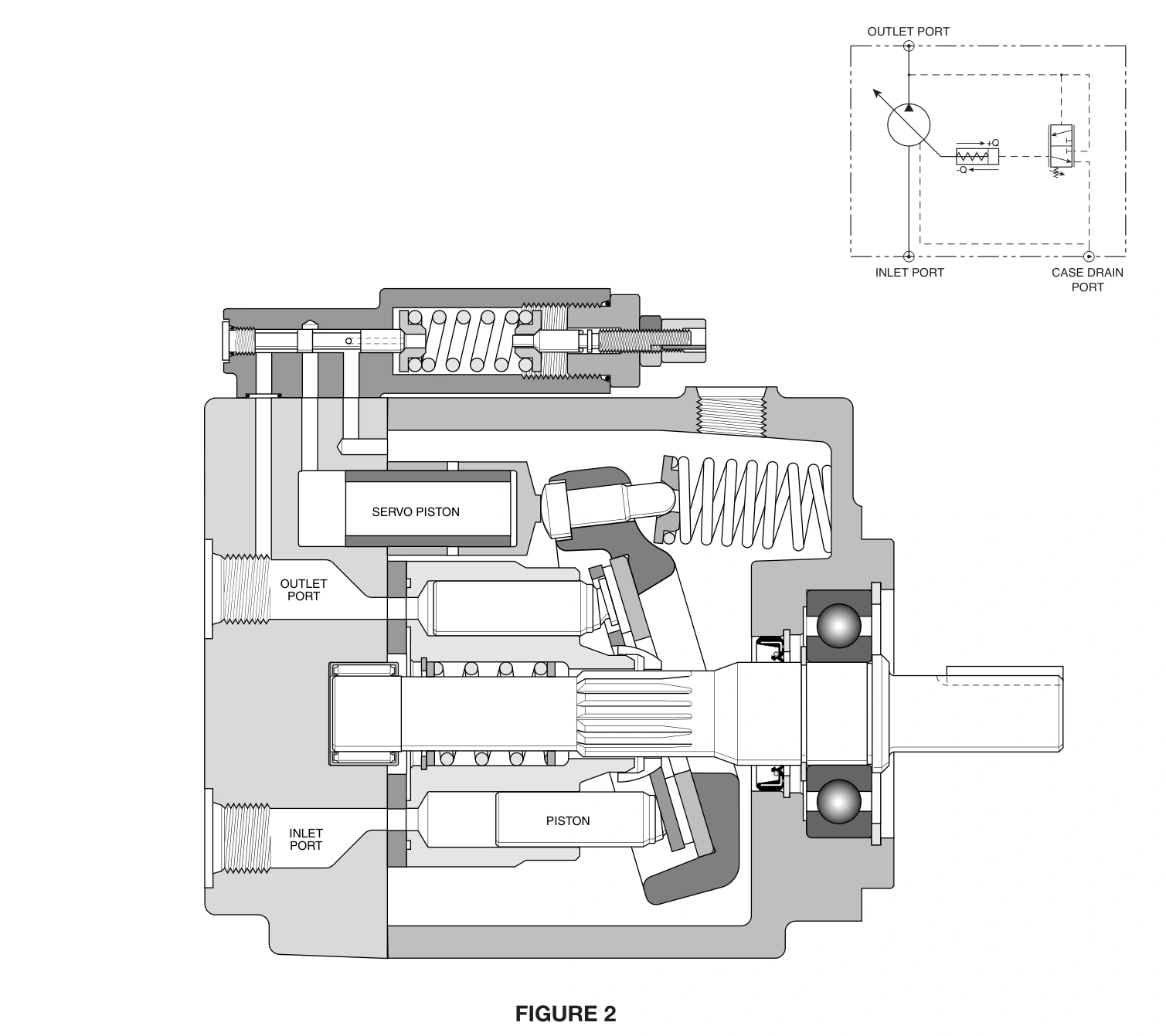
This differs from a fixed-displacement pump delivering excess flow over a relief valve. Near pressure holding, a compensated pump supplies the applicable leakage and control demand. Minimum flow and power remain model-specific.
Reduced flow at an end stop can be normal
Assume travel requires 30 L/min at 100 bar. At the end stop, pressure rises to a 160 bar setting and sustained motion flow is no longer required. Reducing displacement avoids unnecessary high-pressure delivery.
If an external branch or leakage consumes 2 L/min at 160 bar, its hydraulic power is approximately 0.53 kW. Passing 30 L/min continuously over relief at 160 bar represents about 8 kW, largely converted to heat.
These numbers compare external oil-flow energy. They exclude mechanical losses, internal leakage and control losses; 0.53 kW is not the motor's measured input power.
Reaching the setting during motion also reduces flow
Suppose the increased load requires 170 bar at the original speed, while compensation is set at 160 bar. The pump enters displacement reduction at its setting and cannot maintain the original motion while supplying the required 170 bar force.
High pressure with low flow can therefore reflect the pressure limit operating as intended. Raising the setting requires a full assessment of pump, actuator, lines, valves and motor capability.
If the actuator theoretically needs only 100 bar while the pump reaches 160 bar, investigate throttling losses, a closed path or other loads. Pump pressure does not establish the same pressure at the working chamber.
| Operating condition | Observation | Interpretation |
|---|---|---|
| Actuator stopped with little ongoing demand | Pressure reaches setting; flow falls | Can be normal compensation |
| Required load force exceeds the pressure limit | Limited pressure and reduced speed | Load and pressure setting do not match |
| Low chamber pressure but pump near setting | Large intervening differential | Investigate valves and line losses |
| Delivery does not recover when pressure falls | Persistently slow motion | Assess control, supply and pump condition |
Remote-pressure and load-sensing controls use different signals
Catalog option M uses remote pressure control; option A provides load-sensing flow control. Their signal paths and displacement response are not identical to the basic configuration.
An external remote-pressure valve and its pilot line can affect operating pressure. A load-sensing circuit needs the relevant load signal and metering differential. One compensator's adjustment logic cannot explain every PVP installation.
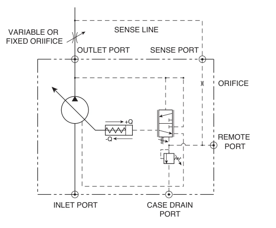
Match the actual control configuration to the circuit drawing. Without that identification, reduced flow cannot be assigned directly to control failure or pump wear.
Observe pressure and speed recovery together
Assume demand starts, outlet pressure falls from 160 to 110 bar and the actuator needs 30 L/min. Pressure compensation should respond to demand with increased displacement, but recovery time and actual delivery require the relevant model and test conditions.
Normal cold speed but reduced hot speed below the pressure limit calls for hot-delivery and leakage assessment. If pressure remains at the limit, load and circuit losses remain important conditions.
Case-drain flow can support investigation only with defined temperature, pressure, speed and applicable limits. One unqualified drain-flow number cannot condemn every PVP, and the drain must not be blocked for comparison.
Travel time can support an initial flow comparison
A 50 cm² cylinder covering 200 mm in 2 seconds averages 100 mm/s, corresponding to approximately 30 L/min effective inlet flow. The same stroke in 4 seconds corresponds to about 15 L/min.
This estimates average effective actuator flow, not pump outlet flow. Branch allocation, leakage and valve restrictions can intervene. Combine it with pump and chamber pressure to establish the load conditions during reduced delivery.
Flow reduction at the setting is normal pressure-compensation behaviour. Distinguish that holding condition from inadequate moving flow, pressure limitation or a control problem using load, measured pressure and effective flow together.