HYDAC KFZP Vane Pump Selection: Flow, Motor and Installation
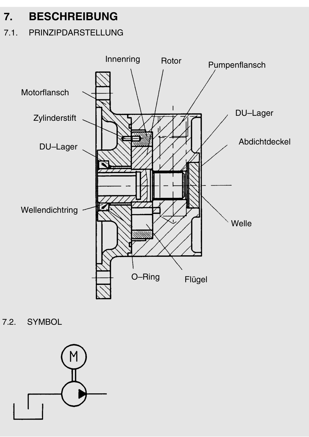
KFZP serves low-pressure filtration, cooling, lubrication and transfer circuits. The OEM FZP/KFZP document identifies it as a vane pump and lists a maximum KFZP working pressure of 16 bar. It is not a substitute for a high-pressure actuator pump.
The website lists models including KFZP-1+2/1.0/P/71/10. This article uses the document's KFZP chapter; numerical duties are illustrative.
Displacement and motor connection
In that ordering structure, 1+2 identifies the size group, P denotes Perbunan seals, 71 identifies the B5 motor connection size, and the final 10 means 10 cm³/rev. Change identifiers such as 1.0 or 1.3 are not motor-power values.
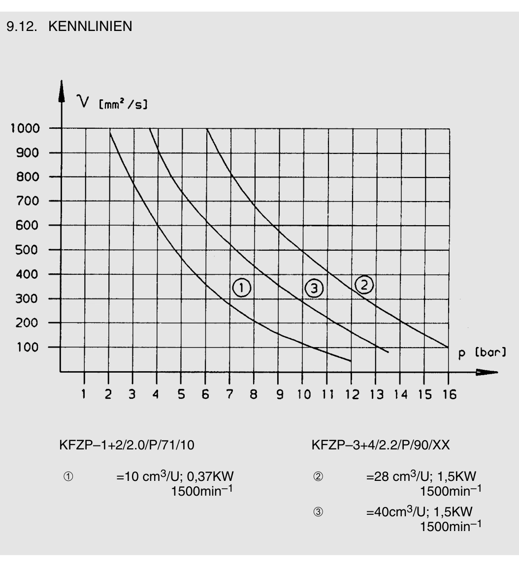
The document also lists the 3+4 group, BG90 connection and displacements including 28 and 40 cm³/rev. A matching motor flange does not establish adequate shaft power.
Calculate flow from displacement and speed
Theoretical flow equals displacement × speed / 1000. At 10 cm³/rev and 1500 r/min it is 15 L/min. Assuming 90% volumetric efficiency gives about 13.5 L/min delivered flow.
This can be assessed for a 12 L/min cooling duty. A 20 L/min requirement needs a different displacement or a properly assessed speed change; a larger motor alone does not change geometric delivery at the same speed.
The referenced KFZP speed range is 1000–2000 r/min. Any speed change also requires inlet and viscosity assessment.
Motor power depends on pressure and losses
At an illustrative 15 L/min and 5 bar, hydraulic power is 0.125 kW. Assuming 65% overall pump efficiency gives about 0.19 kW shaft power, before assessing starting and viscous demands.
At 15 L/min and 16 bar, hydraulic power alone reaches 0.4 kW, exceeding a 0.37 kW motor. Do not combine the document's 0.37 kW example with its maximum pressure independently of the applicable performance curves.
Cold noise and poor flow call for inlet checks
Cold, viscous oil increases losses in small, long or restrictive inlet lines. Improvement after warm-up warrants temperature, viscosity and inlet checks.
The document lists inlet limits of −0.4 bar suction pressure and 0.5 bar positive pressure for the referenced configuration. Maintain design margin and check for air ingress or hose collapse.
Record rotation from the pump marking or drawing's specified viewpoint. Shaft-end and fan-end observations reverse the apparent direction. Qualified personnel should verify rotation after motor or phase changes without prolonged dry running.
| Observation | First checks |
|---|---|
| Matching flange but motor overload | Pressure, viscosity and required shaft power |
| Correct speed but inadequate delivery | Displacement, pressure conditions and internal losses |
| Cold noise that improves warm | Inlet restriction, temperature and air ingress |
| No delivery after motor replacement | Specified rotation, connection and inlet condition |
Select KFZP for a low-pressure circulation duty, calculate flow from displacement and speed, and select motor power for pressure and losses. Maximum pressure, speed and motor examples are not a single combined rating.