Parker PVP: Displacement, Speed and Motor Power
Select PVP displacement and motor power from required flow and operating pressure. Variable displacement changes delivery but does not remove limits imposed by maximum displacement, speed and available shaft power.
Examples use Parker catalogue HY28-2662-CD/US, revised July 2023, and the PVP23, PVP33 and PVP41 sizes. Efficiency figures are calculation assumptions, not guaranteed performance.
Displacement for 40 L/min at 1500 r/min
Assuming 92% volumetric efficiency, required displacement is approximately 40 × 1000 / (1500 × 0.92) = 29 cm³/rev.
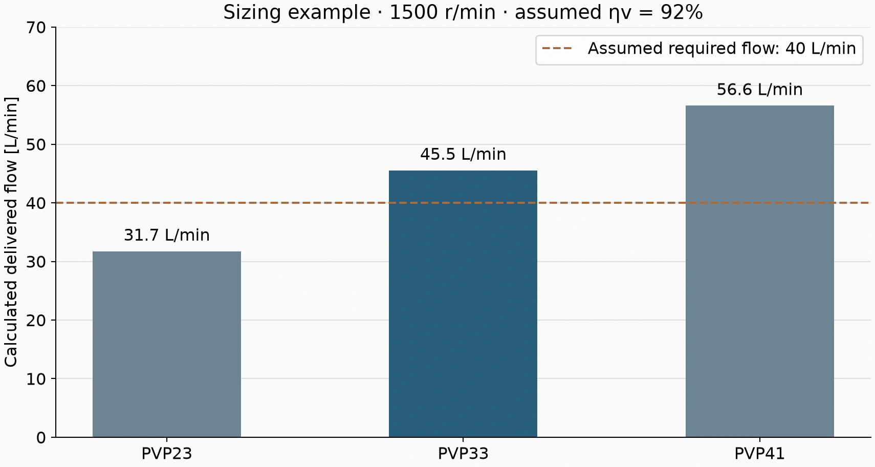
Nominal sizes of 23, 33 and 41 cm³/rev provide approximately 31.7, 45.5 and 56.6 L/min at that speed and assumed efficiency.
PVP23 is below demand. PVP33 can proceed to further checks. PVP41 has capacity but requires assessment of part-displacement operation, control configuration and full-displacement power.
Keep catalogue speed conditions attached
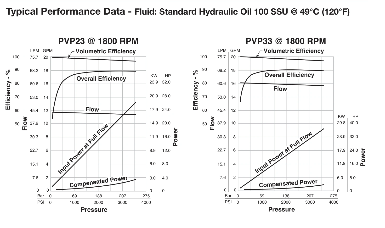
The referenced table lists PVP33 output of approximately 59.0 L/min at 1800 r/min and 39.4 L/min at 1200 r/min. Retain its conditions; do not apply the 1800 r/min output directly to a 1500 r/min motor installation.
Theoretical delivery scales with speed, while actual delivery also depends on pressure, temperature and internal losses. Frequency or variable-speed changes require inlet and permissible-speed checks.
Power for 200 bar and 40 L/min
Hydraulic power is 200 × 40 / 600 = 13.3 kW. Assuming 85% overall pump efficiency gives approximately 15.7 kW shaft power.
A 15 kW motor is already insufficient for that assumed point. Final selection requires actual performance curves, continuous duty, starting conditions and appropriate margin.
A larger pump increases potential full-displacement demand. If its control allows maximum displacement at a relevant pressure, the motor must support that duty or an engineered power-limiting arrangement must constrain it. Do not assume the pump always stops at 40 L/min.
At the example's full 45.5 L/min for PVP33, 200 bar and assumed 85% overall efficiency imply about 17.8 kW shaft power. Size the motor for the maximum duty that can actually occur.
Choose the actual control configuration
| Task | Selection focus |
|---|---|
| Reduce delivery at set pressure | Applicable pressure-compensator configuration |
| Match flow to changing demand | Actual flow-control or load-sensing arrangement |
| Limit drive loading | Applicable power-control option across the duty range |
| Replace an existing pump | Complete control code, rotation, shaft and connections |
Reducing displacement after a clamp reaches pressure can be normal pressure-compensator operation. Reduction during rapid feed warrants checking settings, load pressure and control signals.
The PVP family name alone does not establish that every control function is fitted.
Complete the installation checks
PVP23/33 rotation codes use the shaft-end viewpoint. Record that perspective and match shaft, flange, inlet/outlet connections and applicable case-drain requirements.
Qualified personnel should follow the corresponding start-up and drain instructions. Inlet piping, fluid level, viscosity and drain backpressure remain important even when the motor runs normally.
Size the motor against the machine's duty cycle
A press may have rapid approach, slow pressing and pressure holding. Approach uses relatively high flow at lower pressure; pressing uses higher pressure at lower speed; holding allows the specified compensator to reduce delivery. Calculate each stage separately.
For example, 45 L/min at 40 bar needs 3 kW hydraulic power, while 20 L/min at 200 bar needs about 6.7 kW. If the circuit ensures these are separate duties, combining 45 L/min and 200 bar does not describe the normal pressing point.
However, any permitted state that can produce high flow and high pressure together must be covered by the motor and pump control. Avoid both combining unrelated maxima and overlooking a real high-power duty.
Compare 15 kW and 18.5 kW against more than the target point
The illustrative 40 L/min, 200 bar and 85% overall-efficiency point needs about 15.7 kW shaft power. A 15 kW motor is insufficient; 18.5 kW is a candidate for further duty, ambient, starting and actual-curve checks.
If PVP33 can deliver the example's full 45.5 L/min at that pressure, demand approaches 17.8 kW and margin becomes limited. Assess real efficiency, duty rating and applicable power control.
Where motor power is fixed, the designer can assess a suitable power-control configuration or an engineered operating envelope. Do not change protective settings casually to make a pump run.
Higher speed also increases inlet demand
Speed increases theoretical delivery, but inlet piping must supply the additional oil. Pipe bore, viscosity, strainers and fluid level can limit the arrangement, particularly cold.
If a pump runs smoothly at 1500 r/min but becomes noisy after acceleration without the expected flow increase, investigate inlet supply and conditions before increasing speed again.
Use the relevant size's inlet and speed curves. Do not apply one assumed suction limit across PVP23/33 and larger sizes.
Keep the selection inputs with the order
| Information | Purpose |
|---|---|
| Flow, pressure and duration for each step | Actual operating envelope and power |
| Motor speed, power and duty rating | Delivery and continuous-load assessment |
| Control code and required settings | Compensation, flow or power-control function |
| Fluid, temperature and inlet conditions | Viscosity, inlet and starting assessment |
| Original model, shaft, flange and connection drawing | Replacement compatibility |
These inputs let the supplier identify the limiting step and provide a basis for later speed or load changes.
Calculate displacement from flow and speed, then check shaft power at the maximum actual duty. Variable control does not replace motor, inlet and installation assessment.