MOOG G761: Single, Series and Parallel Coil Connections
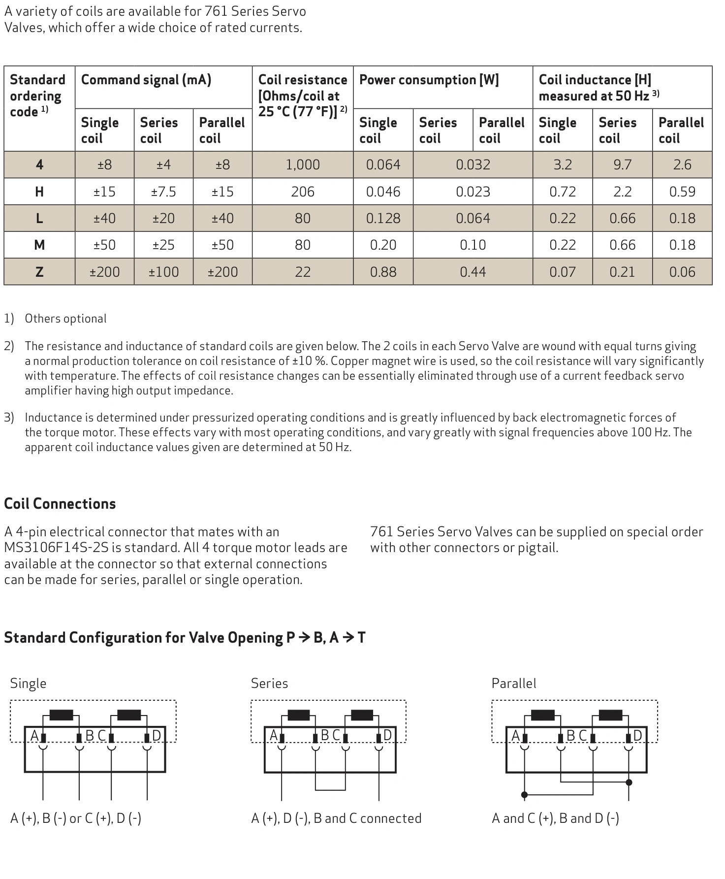
The G761 torque motor can use the applicable single-coil, series or parallel arrangement. Changing the connection changes rated input current, equivalent resistance and amplifier voltage demand. Reconnecting without reviewing the current scale can produce an incorrect drive.
This article uses the MOOG 761 catalog Rev M, April 2024, with coil code L as the calculation example. Its nominal resistance is 80 Ω per coil at 25°C. Other codes and special assemblies require their own data.
Why series rated current differs from single-coil current
In a correctly phased series connection, the same current passes through both coils and both contribute to motor drive. Single-coil operation uses one coil at its applicable rating.
Code L lists ±40 mA single-coil and ±20 mA series. The lower series current reflects the combined coil action; it does not mean the valve receives half its rated opening command.
Parallel operation lists ±40 mA total. With identical coil resistances, each ideally carries approximately 20 mA. Amplifier total current and individual coil current are different quantities.
The same total current can represent different drive levels
At 20 mA, a single L coil receives half its ±40 mA rated current. Correct series operation at 20 mA reaches its rated signal. Parallel operation with only 20 mA total ideally gives 10 mA per coil and half the rated parallel input.
Record coil code, connection, rated current and controller range together during amplifier replacement or restoration. A note stating only 20 mA does not establish rated drive.
Resistance determines the static voltage drop
With two identical 80 Ω coils, equivalent resistance is 80 Ω single, 160 Ω series and 40 Ω parallel. At rated drive, U = IR gives approximately 3.2 V single, 3.2 V series and 1.6 V parallel.
| Code L connection | Rated signal | Equivalent resistance | Static voltage estimate |
|---|---|---|---|
| Single | ±40 mA | 80 Ω | 3.2 V |
| Correct series | ±20 mA | 160 Ω | 3.2 V |
| Correct parallel | ±40 mA total | 40 Ω | 1.6 V |
These are resistive drops at nominal 25°C resistance, not amplifier supply requirements. Inductance, cable and dynamic drive need additional voltage headroom. Do not select a supply solely from 1.6 or 3.2 V.
The catalog notes temperature-dependent resistance of copper windings. A current-feedback amplifier can maintain commanded current while sufficient voltage is available. Voltage limiting can prevent hot or dynamic current from following the command.
Coil phasing determines torque direction
Both coils must contribute in the OEM-specified magnetic direction. Reversing one coil can change the combined drive, while reversing overall drive polarity can change valve action.
In closed-loop equipment, valve direction must agree with feedback direction. Connection checks and direction verification belong in the approved commissioning state, performed by qualified personnel before normal commands resume.
Connector letters and controller channel numbers identify different items. Use the actual OEM connection drawing. The simplified calculations here are not universal terminal-wiring instructions.
Resistance checks do not verify hydraulic performance
After shutdown, appropriate electrical isolation and stored-pressure control, qualified personnel can identify coils and connections using the manual. Account for temperature, lead resistance and OEM tolerance.
The 80 Ω value is nominal at 25°C, with manufacturing tolerance listed for standard windings. A different reading cannot establish failure without those conditions. A clear open circuit, short or abnormal inter-coil difference needs investigation.
Normal resistance supports only part of the electrical assessment. It does not verify pilot condition, main-spool behaviour, null or flow performance. Those require correct drive and defined hydraulic conditions.
Match current range, voltage headroom and control direction
The amplifier must provide the rated current for the connection and adequate voltage for resistance, inductance and wiring. Command scaling, polarity and closed-loop direction must also match the machine.
Changing from a 40 mA single-coil configuration to series requires reviewing the scale against the 20 mA series rating. This example does not authorise applying 40 mA directly to the series arrangement.
Single, series and parallel configurations differ in combined magnetic drive and amplifier current/voltage burden. Establish a matching connection and drive before comparing valve flow or response.