MOOG G761: Selecting Flow and Drive Current
Start with the flow the cylinder needs and the current available from the servo amplifier. These determine whether a G761 can deliver the required speed. On an existing machine, mounting, coil connection and spool function must also match.
For example, the MOOG 761 catalogue, Rev. M, April 2024, places G761-3001B in the 4 L/min flow grade. G761-3001 is a common shortened reference; include the final letter when ordering the corresponding configuration.
How current moves the spool
G761 uses a two-stage nozzle-flapper design. Torque-motor current changes pilot pressure, moving the main spool. A feedback member follows the spool and returns its position change to the torque motor.
Cylinder positioning also uses machine feedback. On a press, for example, a displacement sensor measures slide position. The controller adjusts valve current to reduce position error, and G761 changes oil flow. A loose sensor or reversed feedback direction can therefore affect positioning even with a serviceable valve.
What 4 L/min means for cylinder speed
The rated condition is 35 bar per metering land, or 70 bar across the two lands in a standard four-way flow path. Higher load pressure leaves less differential across the valve, reducing flow at the same opening.
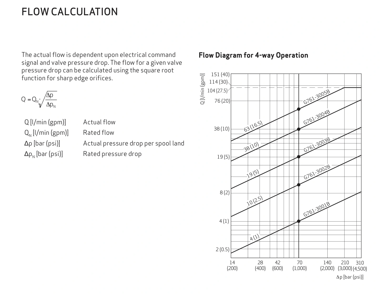
For an illustrative cylinder area of 10 cm², a target speed of 50 mm/s requires 3 L/min. A 4 L/min configuration covers that demand at its rated condition.
If total valve drop falls from 70 to 35 bar, estimated flow becomes 4 × √(35/70) = 2.83 L/min, giving approximately 47 mm/s. This assumes adequate pump delivery and operation within the valve's applicable range.
A machine that runs normally unloaded but slows under greater load calls for supply and load-pressure measurements during motion. Insufficient differential may prevent the target speed even at a larger command.
L coils in series use a ±20 mA rated signal
For coil code L, the catalogue lists ±40 mA for a single coil, ±20 mA for series connection and ±40 mA for parallel connection. Keep each current rating associated with its connection.
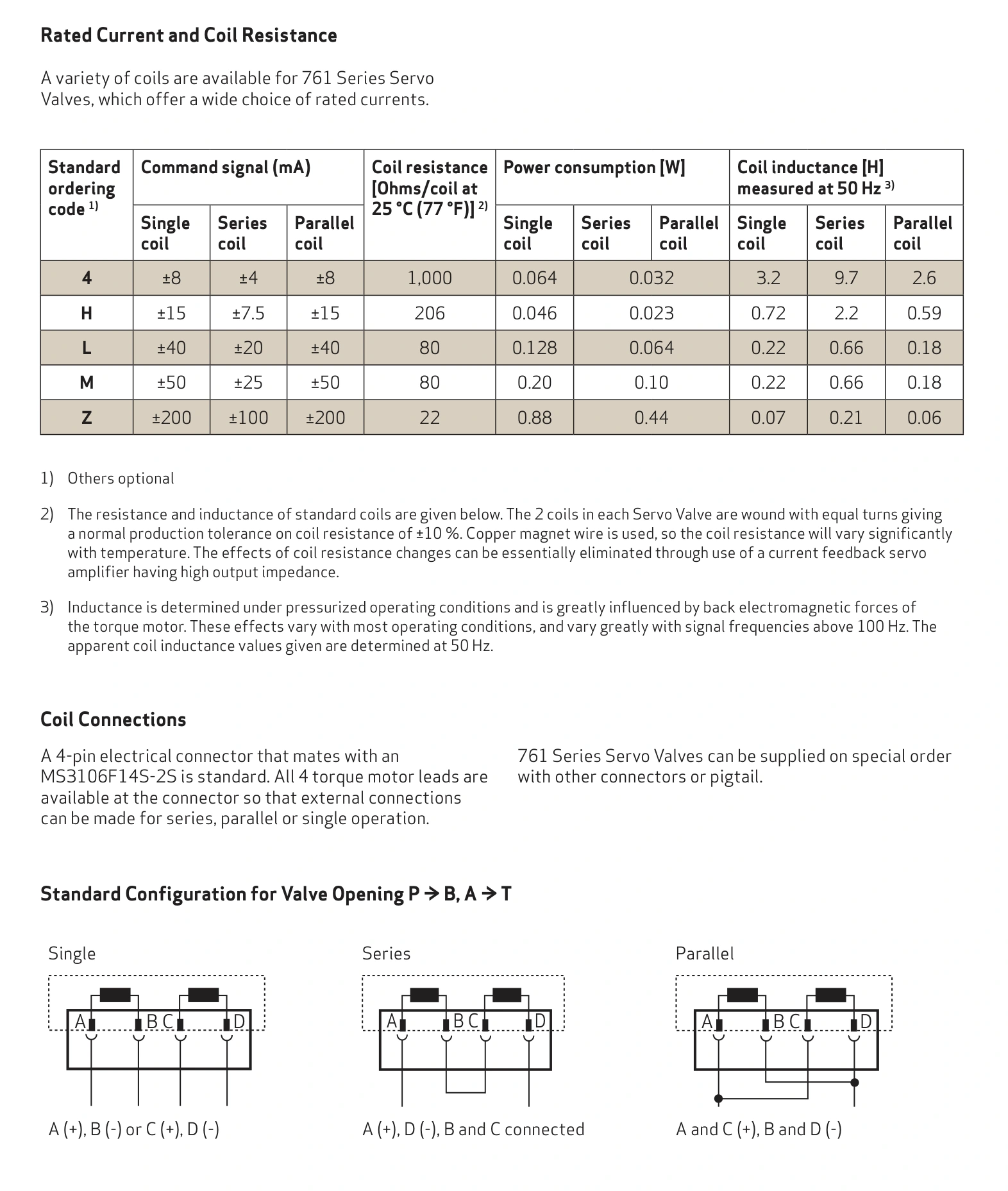
Suppose the original machine uses series-connected L coils and a ±20 mA amplifier range. The same replacement configuration uses the matching current range. Changing to a single-coil connection while retaining that range leaves full command below the single-coil rated current and affects the available flow range.
A PLC's ±10 V command normally enters a suitable amplifier, which produces coil current. During troubleshooting, compare command with actual amplifier output. If command reaches full scale while current remains limited, investigate the drive and wiring.
Keep the original installation record
The mounting pattern is ISO 10372-04-04-0-92. Locating features, seals, pilot supply and spool null configuration also matter. Retain the original nameplate, manifold drawing and wiring photographs.
| Observation or task | First checks |
|---|---|
| Normal unloaded, slow under load | Supply, load and return pressures during motion |
| Full command but insufficient speed | Actual current, coil connection and flow grade |
| Direction changes after replacement | Specified polarity, work ports and machine feedback direction |
| Replacement on the existing manifold | Complete model, mounting, seals and pilot arrangement |
Calculate flow from cylinder area and speed, select a flow grade at the available differential, and match amplifier current to the coil code and connection. These checks connect G761 selection to the machine's actual speed requirement.