MOOG G631 vs G761: What an Existing Machine Must Match
G631 and G761 are both two-stage mechanical-feedback flow-control servo valves. Their flow ranges overlap, but their mounting and electrical configurations differ. Similar flow capacity does not make them direct replacements.
This comparison uses April 2024 catalogs: 631 Rev. R and 761 Rev. M. The website's G631-3008B and G761-3001 still require their own complete configuration records; a series table does not define an undocumented assembly.
Check mounting before comparing capacity
The 631 catalog identifies ISO 4401-05-05-0-94; the 761 identifies ISO 10372-04-04-0-92. These are different mounting patterns.
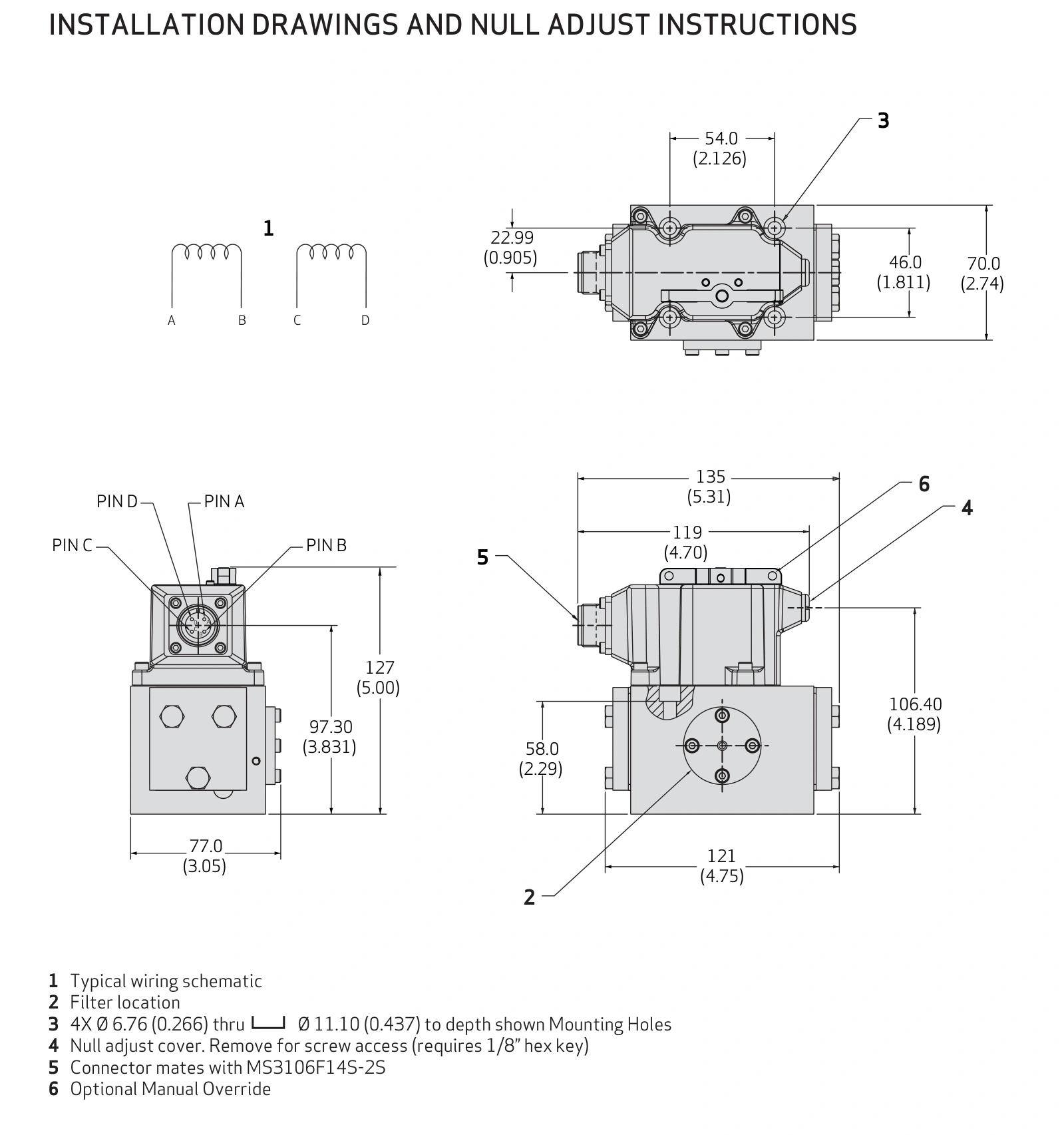
An adapter requires a new review of passages, pressure losses, seals and structural space. It does not match driver or pilot requirements automatically. This is a conversion design rather than a direct substitution.
Use matching reference pressure drops
The 631 standard flow grades are 5, 10, 20, 40, 60 and 75 L/min. The 761 catalog covers 0.5–75 L/min and includes grades such as 4, 10, 19 and 38 L/min. Both use 35 bar per metering land, normally 70 bar total in four-way operation.
Assume demand is 30 L/min. A 40 L/min 631 configuration and a 38 L/min 761 configuration both offer nominal capacity at that reference condition. This establishes only one part of the selection.
At 35 bar total valve drop and the same opening, square-root estimates fall to approximately 28.3 and 26.9 L/min. Both miss the requirement. Reassess supply differential and capacity; changing families cannot provide missing pressure margin.
Match the actual coil and driver configuration
For example, the 761 L coil lists ±40 mA for single-coil operation and ±20 mA in series. The 631 has its own coil and connection choices. Do not transfer the original amplifier current setting across families without checking them.
Record connection, driver full scale, connector definition and actual current. Mechanical fit and an electrical connection do not establish matching spool opening for the same controller request.
Compare dynamic figures under their stated conditions
The 631 catalog lists 18 ms for a 0–100% stroke step. The 761 catalog lists less than 8, 6 and 4 ms for standard, high and very-high response configurations. Compare pressure, version and input amplitude; the fastest option is not the specification of every G761.
For slower-cycle machines, mounting, electrical compatibility, flow and stability usually establish feasibility first. High-dynamic applications also need frequency-response and complete control-loop review.
| Check | G631/631 reference | G761/761 reference |
|---|---|---|
| Design | Two-stage mechanical feedback | Two-stage mechanical feedback |
| Mounting | ISO 4401-05-05-0-94 | ISO 10372-04-04-0-92 |
| Flow examples | Standard grades from 5 to 75 L/min | Grades including 4, 10, 19 and 38 L/min |
| Electrical selection | Complete 631 coil configuration | Complete 761 coil configuration |
| Replacement approach | Match the existing assembly first | Review cross-family use as a conversion |
Slow positioning and rapid tracking favour different checks
Consider two illustrative duties. A clamp or slow positioning mechanism moves over several seconds and needs adequate speed and stable stopping. Flow capacity, low-speed behaviour and the existing amplifier come first. If the installed G631 already meets these requirements, a faster valve may provide little benefit compared with the mounting and control changes required.
A mechanism with frequent reversals or rapid position tracking places more weight on valve response. The listed 761 response configurations have shorter step times than the 18 ms listed for 631, making them candidates for further assessment. Check the specific frequency-response curves, input amplitude and machine load; step time does not directly establish allowable machine cycle frequency.
For example, if testing shows that valve response delay consumes a significant part of a test mechanism's tracking time despite adequate flow, assessing a faster 761 configuration is relevant. If controller filtering, hydraulic compliance or load inertia dominates the delay, a faster valve alone may offer limited improvement.
Fine adjustment and large-cylinder travel need different flow grades
The 761 family includes smaller flow grades that can be considered for fine adjustment. A cylinder area of 10 cm² needs only 0.3 L/min at 5 mm/s, compared with 3 L/min at 50 mm/s.
An oversized flow grade can concentrate the required operating range into a small command region, making drive noise, null offset and friction more significant for low-speed motion. Assess null characteristics and drive resolution alongside rated flow.
A 100 cm² cylinder moving at 50 mm/s needs 30 L/min. Here, compare larger configurations at the available pressure drop. The earlier 40 and 38 L/min examples provide only about 28.3 and 26.9 L/min at 35 bar total valve drop, both below demand.
| Duty | Main requirement | Practical comparison |
|---|---|---|
| Existing machine meeting a seconds-long cycle | Restoration, low-speed stability and drive compatibility | Prefer the existing series and configuration |
| Small cylinder with fine adjustment | Small flow grade, null characteristics and current resolution | Consider the smaller grades available in 761 |
| Rapid reversal or trajectory tracking | Specific frequency response and machine control capability | Assess the faster 761 configurations |
| Fast large-cylinder travel | Flow at actual differential and pump delivery | Calculate demand for either family before comparing response |
For an existing G631 installation, check a matching assembly first. Consider G761 only after confirming mounting, electrical, pilot, flow and dynamic requirements. Similar flow alone does not establish interchangeability.