MOOG G761: Normal Drive Current but Slow Cylinder Motion
Rated coil current verifies one part of the drive requirement. It does not establish rated cylinder flow. Flow also depends on coil connection, actual valve response, operating differential and pump delivery. Assess current against the actual coil connection; measured travel time provides an estimate of effective chamber flow.
This article uses the MOOG 761 catalog Rev M, April 2024, and the 761 installation manual. The 38 L/min reference below illustrates pressure effects and is not a common rating for every G761 assembly.
Single-coil and series-connected current are different references
The catalog lists rated signals separately for each connection. For coil code L, they are ±40 mA single-coil, ±20 mA series and ±40 mA total parallel input. The same displayed current does not produce an equivalent drive in every connection.
A series-connected L configuration assessed against another connection's scale cannot be declared correctly driven from the number alone. Conversely, 20 mA in a single L coil does not represent its ±40 mA rated drive simply because 20 mA is rated for the series arrangement.
Match the product record, actual wiring and amplifier configuration. Do not infer rated current from the G761 assembly number alone. Different coil codes have different resistance, and a ±10 V controller command is not a direct coil-current reading.
| Code L connection | Catalog rated signal | Important distinction |
|---|---|---|
| Single coil | ±40 mA | One specified coil is driven |
| Two coils in series | ±20 mA | The same current passes through both |
| Two coils in parallel | ±40 mA total | Total input is not current per coil |
These values apply to the cited L code, not to H, M, Z or special configurations. Qualified personnel should verify drive and wiring; do not experiment with connections during operation.
Rated flow uses 35 bar per metering edge
The 761 catalog uses a rated differential of 35 bar per spool land. For the common symmetric four-way comparison, two active edges give 70 bar total. Keep per-edge and total pressure references consistent.
Assume a valve rated at 38 L/min under those conditions. At the same opening, reducing available differential per edge from 35 to 10 bar gives approximately 38 × √(10/35) = 20.3 L/min.
With an effective cylinder area of 50 cm², those flows correspond to approximately 126.7 and 67.7 mm/s. Reduced differential can nearly halve speed even when the drive reaches its specified value.
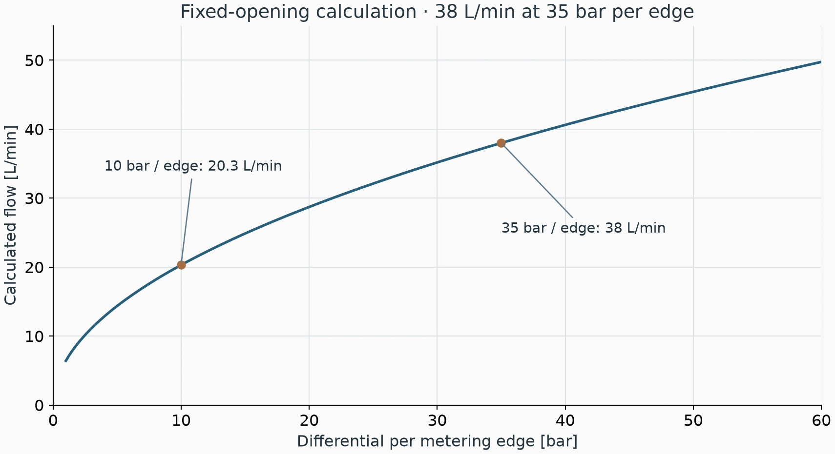
If unloaded motion is fast but loaded motion is slow, measure the relevant valve and cylinder pressures. Pump outlet pressure is not itself the metering differential; load and return pressure consume part of the available pressure budget.
More current cannot replace missing pump delivery
Suppose the valve can pass 30 L/min at the current opening and differential, but only 18 L/min remains available to this branch. With a 50 cm² working area, ideal speed is limited to about 60 mm/s before accounting for leakage and other losses.
On a shared power unit, compare single-axis and simultaneous motion. If target speed is available alone and falls when another axis operates, investigate flow allocation and the pump's pressure-flow capability first. A larger valve cannot create missing supply flow.
A variable pump may reduce displacement under pressure or power limiting. Use delivery at the actual pressure, speed and temperature, rather than assuming low-pressure nameplate flow remains available.
Persistent low speed and startup delay indicate different conditions
A late start followed by normal travel points toward the response-building process. Persistently slow travel is associated with delivered flow, metering differential and valve response. Records should distinguish the two symptoms.
The 761 manual includes contaminated pilot inlet filtration among possible causes of following problems, increased threshold and poor response. This supports checking pilot conditions; it does not establish a blocked filter from slow response alone.
Current, pressure and position traces reveal response differences. Established current with delayed pressure and motion calls for pilot-supply, filtration and valve-response assessment. More current or repeated shock commands cannot replace those tests.
Calculate effective flow from travel time
For a 200 mm measuring section, about 1.58 seconds initially and 2.95 seconds later imply approximately 38 and 20.3 L/min with the assumed 50 cm² area. Similarity to the pressure example does not prove that differential is the actual cause.
Compare actual current, supply pressure, both chamber pressures and other-axis operation during that interval. Include temperature if the problem appears hot. Records need comparable load and command before changes can be assigned to a particular stage.
| Observation | Relevant checks |
|---|---|
| Slow since valve or amplifier replacement | Coil code, connection and drive configuration |
| Fast unloaded, slow loaded | Remaining metering differential and chamber pressures |
| Fast alone, slow with other axes | Actual pump flow and branch allocation |
| Delayed start, then normal speed | Pilot response, filtration and startup conditions |
| Normal cold, persistently slow hot | Hot delivery, leakage and signal records |
Reaching the specified G761 current does not remove flow limits imposed by pressure differential or pump delivery. Persistent low speed requires a flow and pressure assessment; startup delay calls for pilot-condition and response testing. Coil configuration, current, pressure and travel-time records together provide the basis for circuit adjustment or valve repair.