MOOG 730: Flow, Current and Replacement
730 is a two-stage mechanical-feedback flow servo valve with a double-nozzle flapper pilot, dry torque motor and spool-and-bushing main stage. It uses an external driver to supply coil current and is relevant to machines with traditional servo amplifiers.
Replacement problems often involve a changed coil connection despite matching flow, or mismatched rated pressure-drop conditions despite matching current. This article uses Rev. G, April 2024.
How mechanical feedback positions the spool
Torque-motor current moves the flapper, changing pilot differential and moving the main spool. A cantilever feedback spring returns spool displacement to the pilot, establishing a position corresponding to input current.
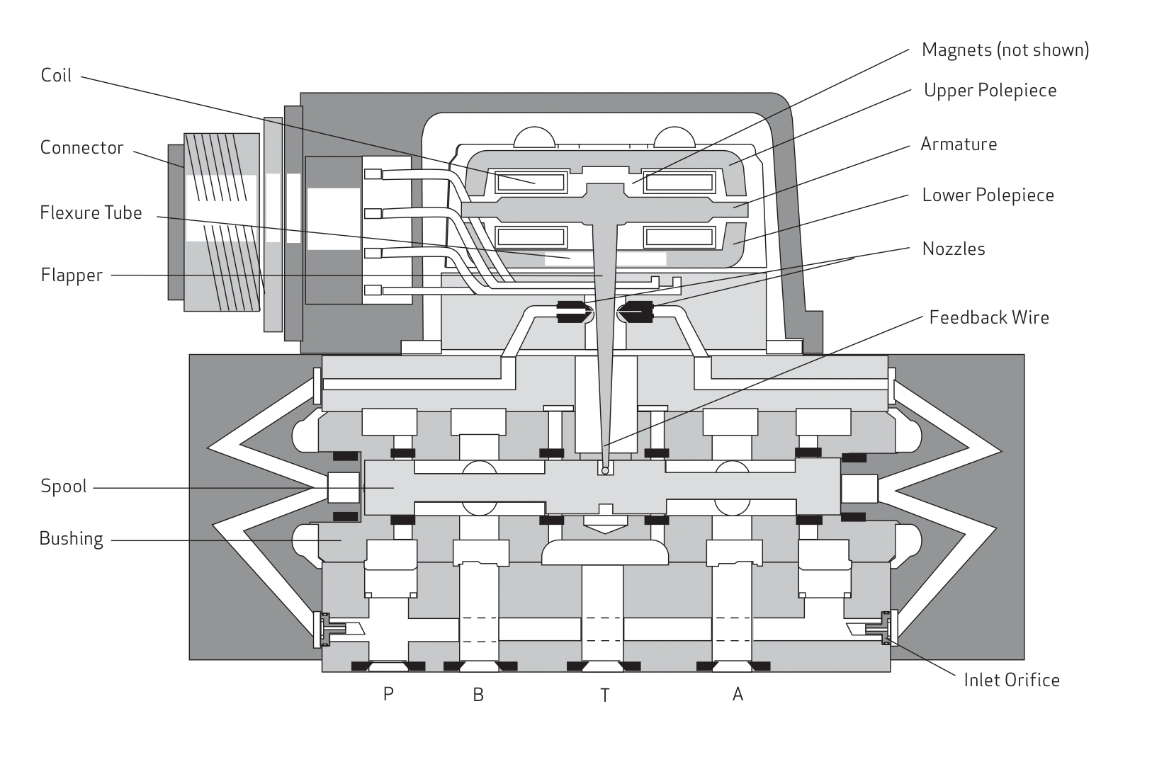
For cylinder positioning, the controller converts position error into a drive command. The external amplifier supplies current, and 730 changes flow. A limited amplifier output can prevent flow from increasing even while displayed command rises.
Convert rated flow into cylinder speed
Common catalogue grades include 4, 10, 19 and 38 L/min at 35 bar per metering land, or 70 bar total across a standard four-way path.
An illustrative 40 cm² cylinder area moving at 50 mm/s needs 12 L/min. A 10 L/min grade is insufficient at that rated condition, while 19 L/min has margin.
At 35 bar total valve drop, estimated flow from the 19 L/min grade becomes about 13.4 L/min at the same opening. Further load increases may reduce differential enough to miss the target. Allow for actual operating conditions when sizing.
Coil code and connection determine current
| Coil code | Single coil | Series | Parallel |
|---|---|---|---|
| H | ±15 mA | ±7.5 mA | ±15 mA |
| L | ±40 mA | ±20 mA | ±40 mA |
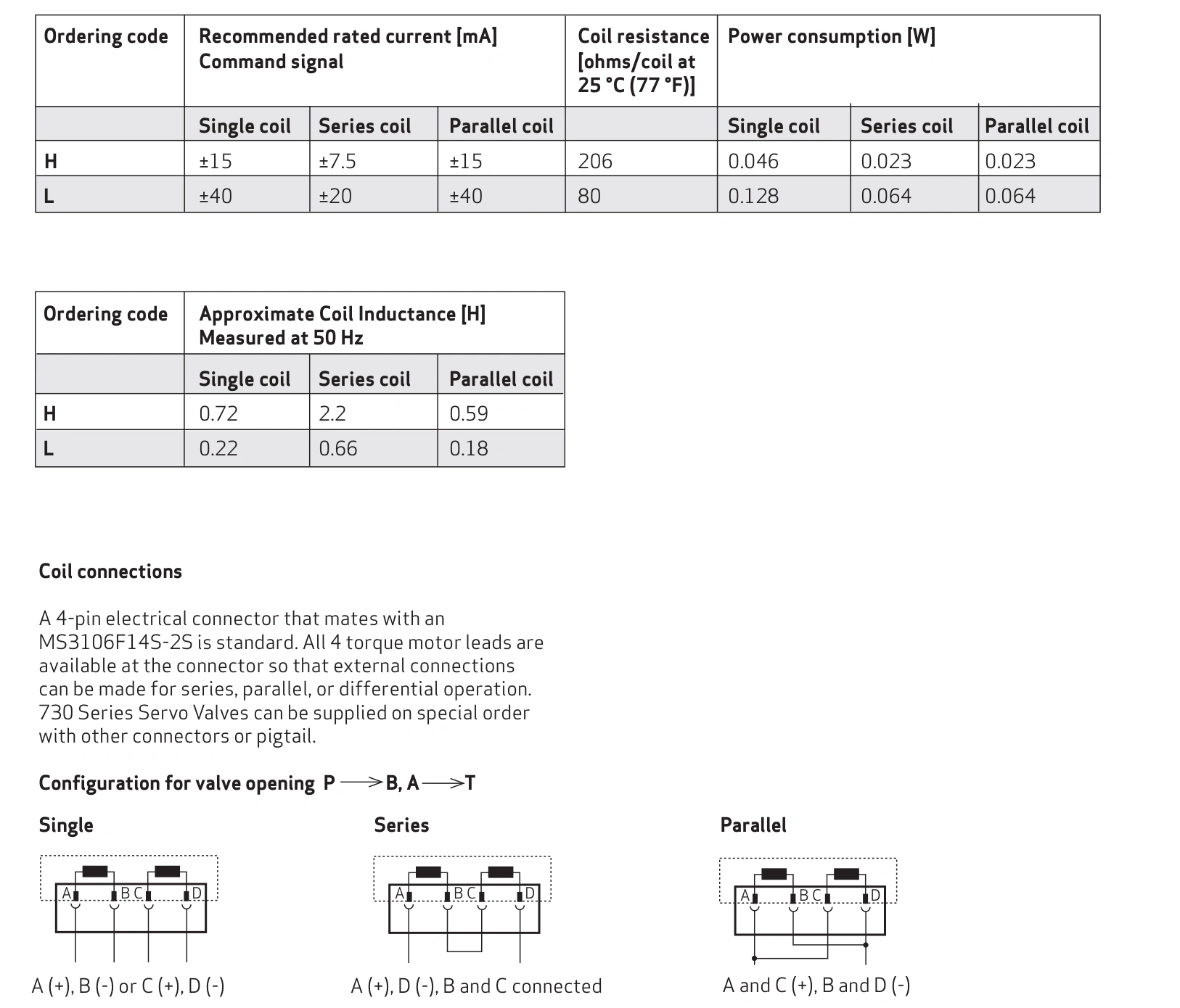
If the original machine uses series-connected L coils with a ±20 mA amplifier, changing to a single-coil connection while retaining the output range provides only half that connection's rated current. Both directions may operate but maximum speed may be inadequate.
Compare wiring and measured current before attributing insufficient flow to the hydraulic stage. PLC voltage command and torque-motor current are different interfaces.
Standard and high-response versions
For the 4, 10 and 19 L/min grades, listed full-stroke step times are 8 ms standard and 7 ms high response. For 38 L/min they are 9 and 7.5 ms, at the stated 210 bar system-pressure condition.
A seconds-long clamp action prioritises flow, stable low-speed operation and driver compatibility. A small-stroke tracking mechanism warrants closer assessment of frequency response, signal amplitude and load. Step time describes valve response under specified conditions.
Preserve the original interface relationships
Standard versions are rated for 210 bar. Other pressure options do not apply to every 730. The mounting designation is ISO 10372-04-04-92; use the dedicated drawing for locating features, ports and seals.
A common mounting standard does not establish matching null overlap, polarity, pilot supply or connector configuration. Retain the complete original model and wiring photographs for comparison.
Select flow grade at the actual differential and match current to coil connection. For inadequate motion, compare actual current with available hydraulic differential to separate drive limitations from flow limitations.