MOOG D661 vs D634: Which Servo Valve Fits the Machine?
The MOOG D661 and D634 are available in NG10 size with integrated electronics and spool position feedback. The D661 uses hydraulic force generated by a pilot stage to move its main spool. The D634 moves its spool directly with a force motor. This difference changes the requirements for pilot supply, electrical power and the machine circuit.
This comparison covers the ServoJet-piloted D661-G…A and the analog-interface D634, including flow, response and operating conditions.
Hydraulic spool drive versus direct motor drive
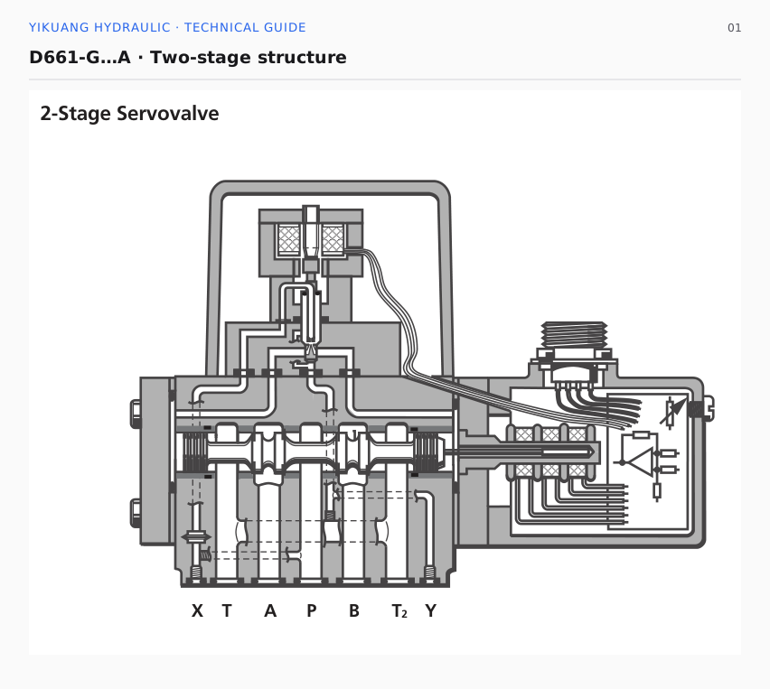
In the D661-G…A, the electronics control the ServoJet pilot stage, which changes pressure at the two ends of the main spool. A position transducer measures main spool position, and the electronics adjust the pilot stage to correct position error.
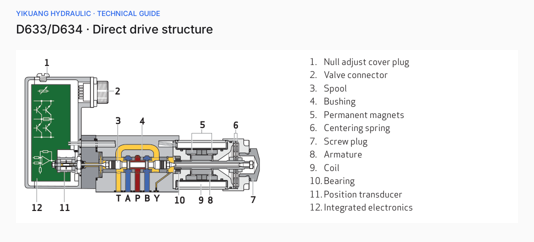
The D634 permanent-magnet linear force motor moves the spool directly. Its position transducer feeds spool position back to the electronics. No pilot oil is needed to drive the spool.
The difference matters during low-pressure movements. With an internally supplied D661, insufficient main supply pressure can reduce the hydraulic force available to move the main spool. The D634 has no pilot-pressure requirement, although moving the cylinder load still requires sufficient main-circuit pressure and flow.
| Item | D661-G…A | D634 |
|---|---|---|
| Size | NG10 / ISO 4401 Size 05 | NG10 / ISO 4401 Size 05 |
| Spool drive | ServoJet pilot stage and hydraulic main stage | Permanent-magnet linear force motor |
| Position control | Integrated closed-loop spool position control | Integrated closed-loop spool position control |
| Rated flow | 20, 40, 80, 90, 120, 160 and 200 L/min | 60 and 100 L/min |
| Rated flow condition | 35 bar pressure drop per spool land | 35 bar pressure drop per spool land |
| Pilot supply | Check internal or external supply configuration | No pilot supply required |
| Supply voltage | 24 VDC; permissible range 18–32 VDC | 24 VDC; permissible range 18–32 VDC |
How much flow can each valve deliver?
The D661-G…A has rated flows from 20 to 200 L/min; the D634 offers 60 and 100 L/min. Both use 35 bar pressure drop per metering edge. A typical four-way path passes through a supply and a return edge, giving a total rated valve pressure drop of 70 bar.
A machine requiring 100 L/min does not automatically need a valve rated at 100 L/min. Pump pressure must cover the load, piping and valve losses. If the pressure drop available across the valve is below the rated condition, flow at the same opening falls and the cylinder slows down.
Calculate required flow from cylinder area and target speed. Subtract load pressure and other losses from supply pressure to find the pressure drop available across the valve. That operating point determines whether a rated flow is sufficient.
A cylinder needs 80 L/min: is the D634 large enough?
The following is a calculation example.
A test machine has a 100 mm cylinder bore and requires an extension speed of 170 mm/s. Flow into the full-bore chamber is approximately:
Q = π × 0.1² / 4 × 0.17 × 60000 ≈ 80 L/min
Assume a pump outlet pressure of 160 bar, a load pressure of 110 bar and combined piping and other passage losses of 15 bar. The total pressure drop available across the valve is approximately 35 bar.
A 100 L/min D634 is rated at 70 bar total valve pressure drop. Using a simplified pressure-drop model and the square-root relationship at the same opening, estimated flow at 35 bar is:
Q ≈ 100 × √(35 / 70) ≈ 71 L/min
That flow produces an extension speed of approximately 150 mm/s, below the required 170 mm/s. Despite its 100 L/min rating, the valve cannot provide the target speed in this calculation.
For a 120 L/min D661-G…A under the same assumptions:
Q ≈ 120 × √(35 / 70) ≈ 85 L/min
On this flow estimate, the 120 L/min D661 is the better fit. Its estimated 85 L/min covers the 80 L/min demand, but the margin is small and leakage and oil-temperature changes must also be considered.
What changes during low-pressure movements?
Some machines operate normally during high-pressure processing but move slowly during low-pressure rapid approach. With an internally piloted D661, check whether pilot pressure is sufficient during that low-pressure phase.
For example, a machine may unload the main supply while waiting and rebuild pressure at startup. If pilot oil comes from that same supply, spool movement is affected by the pressure buildup. External pilot supply separates the pilot supply from the main circuit, using the appropriate X-port configuration and a separate source.
The D634 force motor drives the spool without waiting for pilot pressure to build. Its hydraulic arrangement is simpler where main pressure varies frequently, low-pressure movements are common or pilot piping is difficult to accommodate.
The D634 still needs enough main-circuit pressure to move the load. Motor force that moves the spool does not make low-pressure oil capable of moving a heavy cylinder load.
Y connections and return backpressure
D661 pilot return routing depends on configuration. Check the external pilot supply X connection and drain Y connection separately. Higher Y backpressure reduces the pressure differential available to the pilot stage and affects main spool drive.
Although the D634 does not need pilot supply, its Y leakage connection has installation requirements. Follow the drawing for the selected valve rather than omitting the drain because it is direct-drive.
During rapid cylinder retraction, return flow can considerably exceed pump delivery. Return passages, the manifold and filters can increase backpressure. Pressure limits for P, A and B cannot be applied directly to T or Y.
Even with an NG10 mounting interface, check additional return ports, drain holes and manifold passages. Matching mounting holes establish only part of the mechanical fit.
What do 8 ms and 20 ms actually tell you?
Different D661-G…A flow groups have typical 0–100% spool-stroke response times of 8, 14 and 18 ms. Test conditions include 210 bar pressure, 32 mm²/s viscosity and 40°C oil temperature.
The D634 response from zero to 100% spool stroke is no more than 20 ms at 140 bar system pressure, 32 mm²/s viscosity and 40°C oil temperature.
The pressures differ, and the D661 figures refer to different flow groups. An 8 ms figure does not describe every D661, nor does it establish that the installed machine will move more than twice as fast as one using a D634.
Step response helps describe a rapid cylinder reversal. Strip guiding, vibration testing and continuous trajectory tracking also require amplitude and phase response curves at the actual signal amplitude. These movements need both sufficient tracking and acceptable lag.
Machine speed also depends on load, piping volume, fluid compressibility and controller settings. A fast spool can still accompany slow cylinder motion when supply flow is insufficient or the load is too high.
Both use 24 V, but wiring can differ
Both valves use 24 VDC with an allowable range of 18–32 VDC. The D634 motor directly drives the spool, so power capacity, peak current and cable voltage drop must suit the selected valve.
When replacing a valve, match power, command, feedback and enable terminals individually. If the controller supplies ±10 V but the new valve receives 4–20 mA, a connector that physically fits does not make the original command compatible.
After confirming signal type, check terminal positions, polarity and controller scaling. A displayed 50% command must correspond to the voltage or current defined by the valve input.
Spool feedback reports spool position, not cylinder position. A machine controlling cylinder position also depends on its cylinder position sensor and external control loop.
Will the cylinder stop when power is lost?
The D634 uses centering springs, but which ports connect or close after power loss depends on the selected spool and fail-safe configuration.
D661-G…A behavior also depends on pilot pressure and fail-safe design. Loss of electrical power, removal of enable and loss of pilot pressure are separate conditions to check.
For a vertical cylinder or suspended load, a centered spool does not establish long-term load holding. Center flow paths, valve leakage, cylinder leakage and other holding devices together determine whether the cylinder drifts downward.
Preserve the machine's load-holding functions when replacing the valve, and verify stopping and power-loss behavior against machine requirements.
Which machines suit the D661 or D634?
The D661-G…A suits larger flow requirements where a stable pilot supply is available. Its 120, 160 and 200 L/min options cover conditions beyond the D634 standard rated range. Actual delivery still depends on valve pressure drop.
The D634 offers a simpler arrangement where its flow range is sufficient and low-pressure movements are common or pilot piping is inconvenient. Direct motor drive removes pilot-pressure variation from the spool-drive mechanism, while power and signal requirements still need to match.
For an existing machine, NG10 size and rated flow alone do not establish a replacement. Spool characteristics, command range, drain connections, power-loss position and manifold passages must agree. Changing them can change speed, control gain and stopping behavior.
The choice comes down to available flow at operating pressure drop, suitable spool-drive conditions and preservation of the machine's control and load-holding functions.