MOOG D661 Model Codes: Flow, Pilot Connections and Electrical Configuration
Two valves labelled MOOG D661 can behave differently after replacement: insufficient speed, no movement at low pressure or incorrect controller feedback. Different flow codes, pilot connections and electrical configurations can cause these symptoms.
The D661 uses an NG10 mounting interface. The following explains flow, hydraulic and electrical codes using the D661-G…A. Suffixes identify different configurations within the D661 series, and code meanings can change; this table should not be applied indiscriminately to every version.
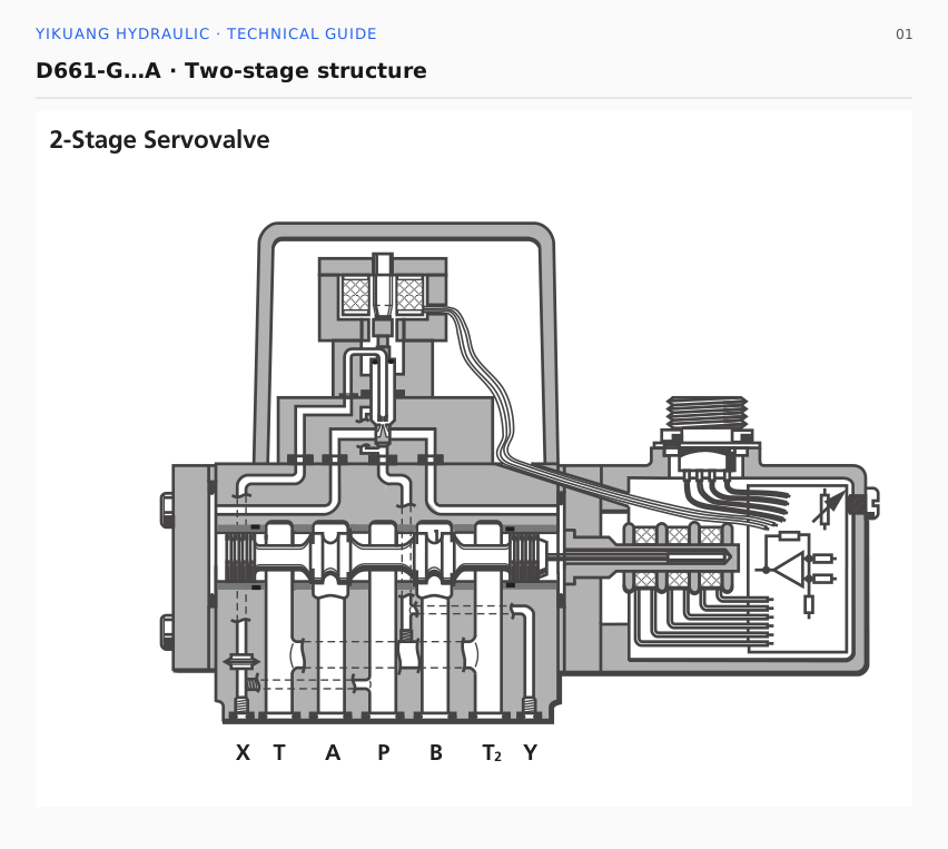
The D661-G…A uses two stages. Its ServoJet pilot creates a pressure differential that moves the main spool. A position transducer returns actual spool position to the integrated controller, forming a closed spool-position loop.
Assembly number and configuration code on the nameplate
The nameplate normally provides a Model Number beginning with D661 and a Type Designation. The model number identifies the factory-assigned assembly. The Type Designation describes flow, spool, pilot connections, seals and electrical configuration.
A number such as D661-4506 identifies a particular assembly. There is no universal digit-by-digit decoding rule for 4506. Flow, signals and pilot connections must come from its corresponding Type Designation and model documentation.
In the G configuration, the flow code identifies metering capacity and the spool code describes the relationship between opening and flow. O denotes near-critical overlap with a linear flow characteristic; S denotes near-critical overlap with a curved characteristic and has applicable flow-range restrictions. Even with the same rated flow, a different spool characteristic can produce a different flow at the same command.
Seal code N denotes NBR and V denotes fluorocarbon rubber. Replacement seals must suit the machine's fluid and operating temperature.
How much flow does code 60 represent?
This D661-G…A table lists two operating points: 70 bar and 10 bar total valve pressure drop. A typical four-way path passes through supply and return metering edges; 35 bar at each edge gives 70 bar total.
| Flow code | Total valve pressure drop: 70 bar | Total valve pressure drop: 10 bar |
|---|---|---|
| 08 | 20 L/min | 8 L/min |
| 15 | 40 L/min | 15 L/min |
| 30 | 80 L/min | 30 L/min |
| 35 | 90 L/min | 35 L/min |
| 45 | 120 L/min | 45 L/min |
| 60 | 160 L/min | 60 L/min |
| 75 | 200 L/min | 75 L/min |
Code 60 corresponds to 160 L/min at 70 bar total pressure drop and 60 L/min at 10 bar. Both figures describe different pressure-drop conditions.
A machine needs 60 L/min: choosing between codes 30 and 60
Assume the movement requires 60 L/min but only 10 bar total pressure drop is available across the valve. At the tabulated operating point, code 30 passes approximately 30 L/min and code 60 approximately 60 L/min. Selecting code 30 because it is rated at 80 L/min at 70 bar can leave the machine short of speed.
Using these catalog operating points, with unchanged cylinder area, reducing inlet flow from 60 to 30 L/min approximately halves speed. Code 60 only just reaches 60 L/min at 10 bar; leakage and other flow consumption have not been included, so additional margin is needed.
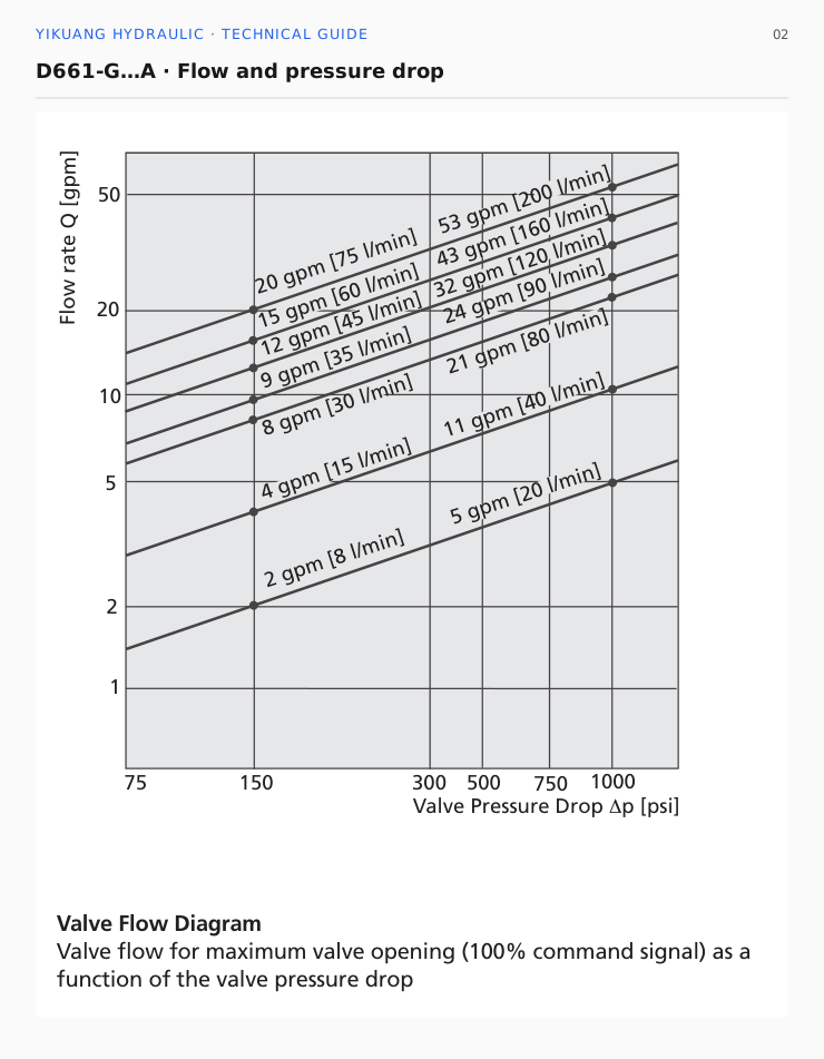
D661-P literature rates flow at 5 bar per metering edge, which differs from the G table's rated condition. A different suffix requires the corresponding interpretation of the flow code.
Increasing supply pressure to raise valve flow also creates more heat. At 60 L/min, a 10 bar pressure drop dissipates approximately 1 kW; 70 bar at the same flow dissipates approximately 7 kW. A larger valve and a higher system pressure have different energy consequences.
A different pilot connection can disrupt low-pressure movement
X is the pilot supply connection and Y is the pilot return connection. The D661-G…A has four pilot connection combinations.
| Code | Pilot supply | Pilot drain |
|---|---|---|
| 4 | Internal | Internal |
| 5 | External | Internal |
| 6 | External | External |
| 7 | Internal | External |
For example, a machine unloads its main pump while waiting and supplies the pilot stage from an independent source. Replacing a code 6 valve, external supply and external return, with code 4 changes the pilot circuit. At low main pressure, the main spool may lack driving force.
Another machine may use a separate external Y return because the common return line has high backpressure. Switching to internal pilot return changes pilot return pressure. The valve's plugs, X/Y passages and T₂ connection must therefore agree with the actual circuit.
For this documented D661-G…A configuration, P, A and B are rated up to 350 bar. With internal Y return, T and T₂ are rated up to 210 bar; with external Y return they can be rated up to 350 bar. These are configuration-specific port limits; the pilot stage has its own pressure range.
The documentation requires pilot supply pressure to exceed pilot return pressure by at least 25 bar. A supply of 40 bar and return of 20 bar provides only 20 bar differential, below that requirement. Reaching 25 bar alone does not establish adequate spool-driving force or compliance with the pilot pressure range at high flow.
Correct 24 V power does not establish correct signals
The D661-G…A uses 24 VDC, with an allowable range of 18–32 VDC. Power supplies the electronics; a separate command tells the valve which direction and how far to open. Spool feedback returns through another signal channel.
| Signal configuration | Input command | Spool position feedback |
|---|---|---|
| D | ±10 V | 2–10 V |
| M | ±10 V | 4–20 mA |
| X | ±10 mA | 4–20 mA |
Configurations D and M both receive ±10 V commands, but their feedback differs. If the controller reads 2–10 V spool feedback, changing to configuration M with 4–20 mA feedback also requires a compatible acquisition module and scaling. Otherwise the displayed position may be incorrect.
For 4–20 mA spool feedback, center is 12 mA; for 2–10 V feedback it is 6 V. These are feedback values, not command values. The 12 mA feedback center must not be treated as the center command for configuration X, whose input is ±10 mA.
Spool feedback reports main spool position. Cylinder position requires a cylinder position sensor; system pressure requires a pressure sensor.
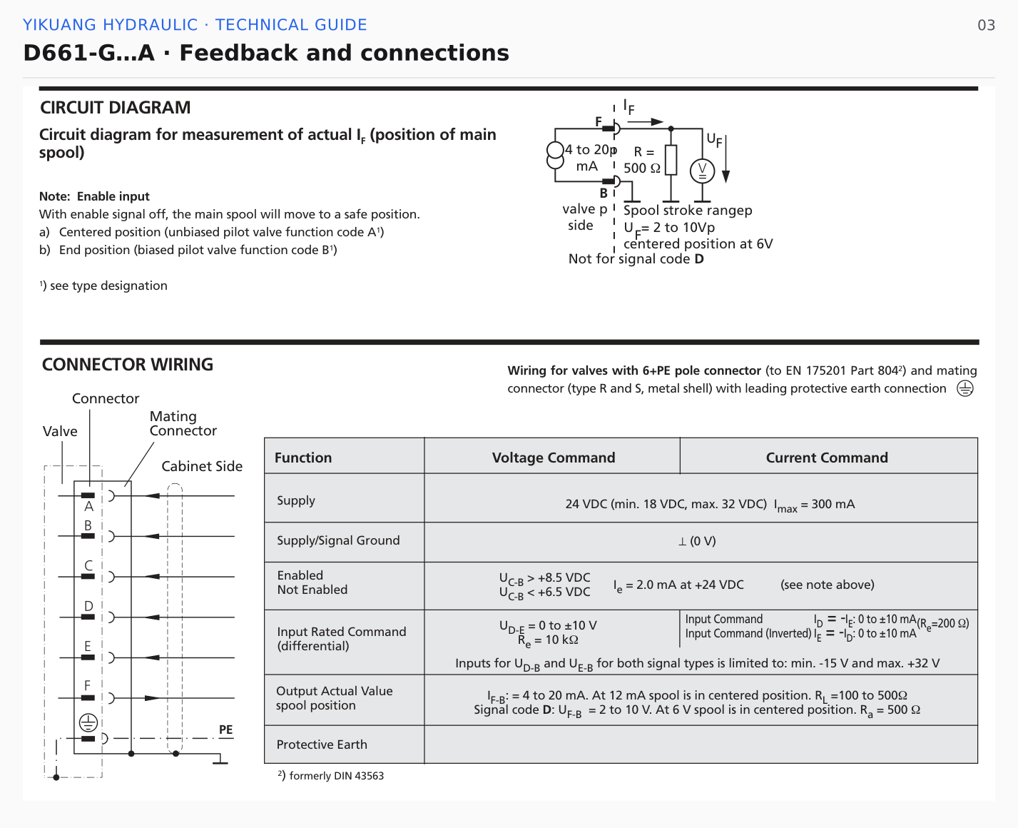
Enable behavior also varies by code. With function code O, pin C is unused. Code A moves toward an adjustable center position when enable is removed; code B moves toward a specified end position. A different function code can change the stopping action on a machine that stops by removing enable.
Power-loss return position uses a separate code. O means no defined fail-safe position; A and B specify port connections and require the appropriate pilot pressure conditions. Electronics may remain powered when enable is removed, whereas power interruption is different. Both stopping conditions must be verified separately.
Response time by flow group
D661-G…A step response is listed by flow group. Frequency response curves also distinguish 10%, 25% and 90% input amplitudes. Small corrections and large movements use different curves.
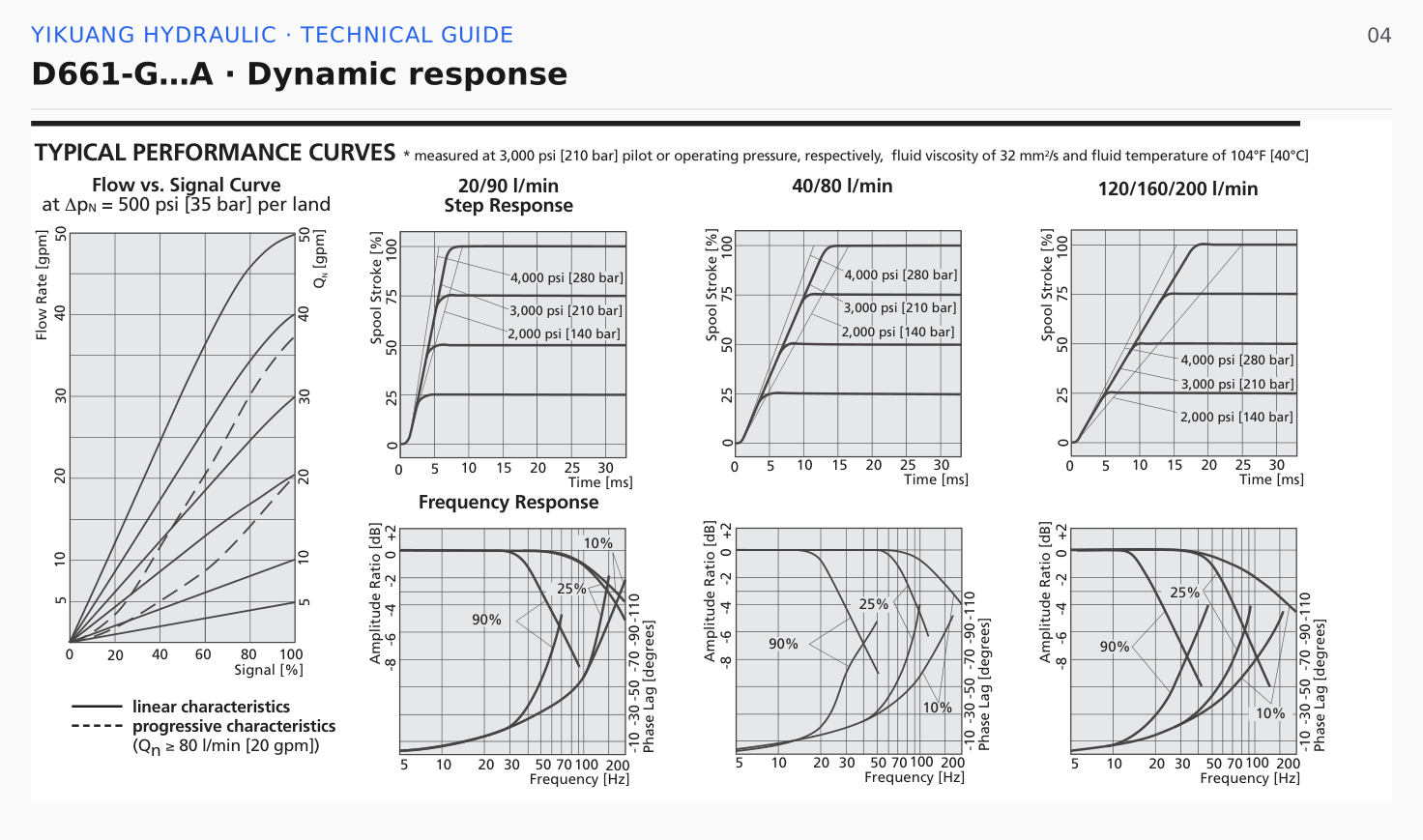
Typical response times are 8 ms for the 20/90 L/min group, 14 ms for the 40/80 L/min group and 18 ms for the 120/160/200 L/min group. The associated test conditions are 210 bar pilot or operating pressure, 32 mm²/s viscosity and 40°C oil temperature.
For example, the 40 L/min version corresponds to 14 ms and the 90 L/min version to 8 ms. A smaller rated flow does not automatically mean a faster response, and the 8 ms figure does not describe every D661. Continuous guiding or cyclic tracking also needs the frequency response and phase lag at the relevant input amplitude.
Fluid cleanliness affects spool positioning and wear. The configuration documentation lists ISO 4406 <18/16/13 for normal operation and <16/14/11 for longer service life, with requirements for upstream high-pressure filtration and clogging indication. Pilot-stage internal filtration and system filtration are separate requirements.
The pilot stage consumes oil. This differs from controlled flow delivered to the cylinder and main-stage null leakage. Compare each leakage or consumption item using its specified test conditions rather than treating all pilot consumption as leakage caused by damage.
What to put on a replacement purchase order
Record the full Model Number, Type Designation, serial number and nameplate photograph. Include the original wiring diagram, manifold passages, supply and return pressures, command and feedback types, enable logic and fault symptoms.
An order stating only D661 and a flow rating can still produce a valve with different hydraulic or signal connections. Specify the complete assembly number, Type Designation, pilot connections and command and feedback types. Attach the original nameplate and wiring diagram for special configurations.
Within the D661 series, a different flow code can change cylinder speed; different pilot connections can change low-pressure behavior; different electrical options can prevent commands and feedback from matching. These details are more useful on a replacement order than the series name alone.
See the MOOG product catalog, or submit the full model and operating conditions through the contact page.