MOOG D661 Versions: P, S, H and Pilot Configuration
D661 can identify nozzle-flapper or ServoJet pilot arrangements, with different main-stage constructions. Letters such as P, S and H must be read in their actual ordering fields.
This article explains the G/S/H/P classification in historical operating instructions CA36197-001, Version 3.0 (01.01), with installation boundaries cross-checked against the available G/S/H instructions. Historical electrical data is not applied universally to later generations.
G, S and H: additional mechanical feedback
The historical instructions describe G as a nozzle-flapper pilot with spool-and-bushing main stage and no additional mechanical feedback. S adds mechanical feedback. H builds on the S arrangement with higher response.
These valves still use electrical main-spool position feedback. Absence of additional mechanical feedback does not make G an open-loop valve.
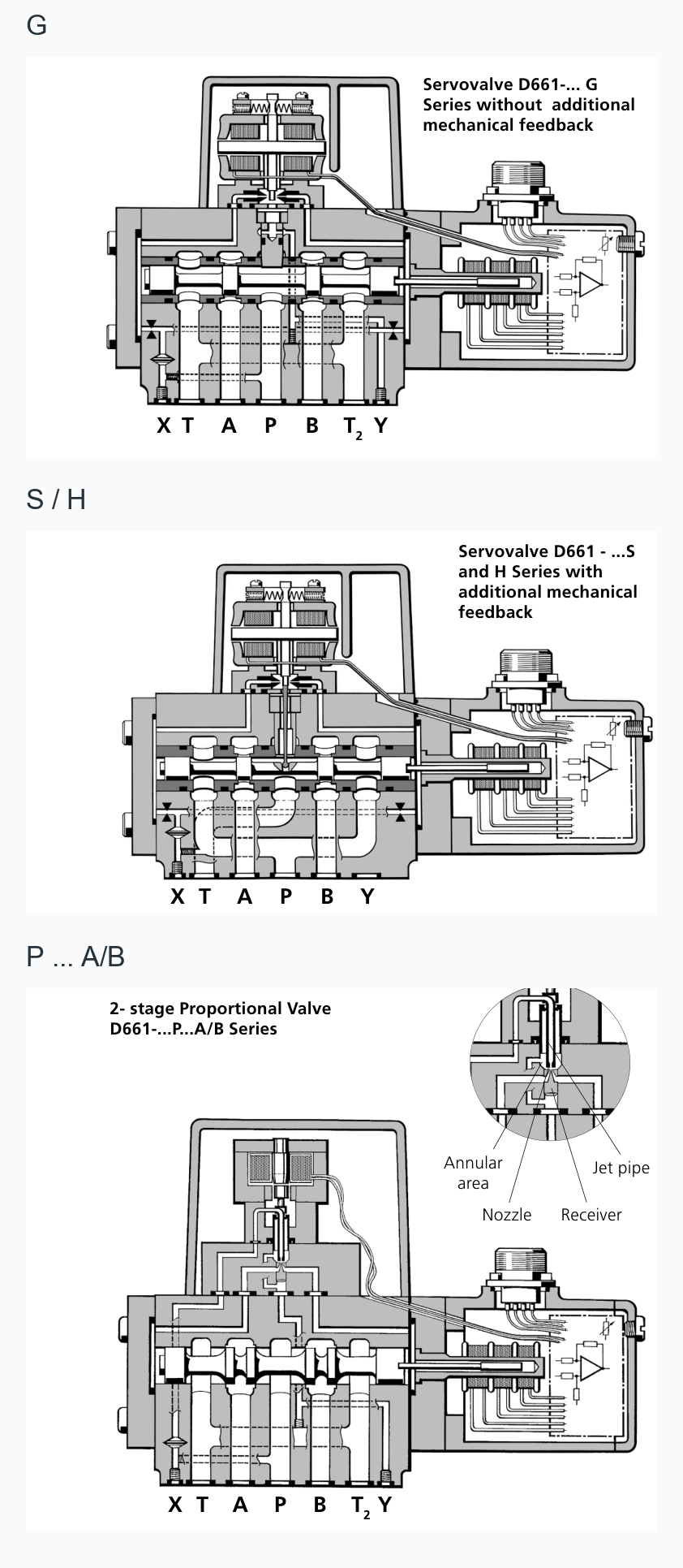
Replacing an S/H arrangement with G requires reassessing loss-of-power behaviour as well as normal performance. The historical S/H mechanical feedback contributes to a specified de-energised position, subject to pilot conditions and configuration. This alone does not establish secure machine load holding.
A P designation still needs its pilot code
Historical P…A/B versions use ServoJet with a spool-in-body main stage. P…F/G uses nozzle-flapper pilot operation and additional mechanical feedback. The P letter alone does not identify the complete pilot arrangement.
| Historical category | Construction | Replacement focus |
|---|---|---|
| G | Nozzle-flapper, spool and bushing, no additional mechanical feedback | Electrical feedback, pilot and de-energised configuration |
| S | Nozzle-flapper, spool and bushing, additional mechanical feedback | Feedback arrangement and specified loss-of-power behaviour |
| H | Higher-response S-type configuration | Dynamic curves and pilot configuration |
| P…A/B | ServoJet, spool-in-body main stage | Rated-flow conditions, pilot and electronics |
| P…F/G | Nozzle-flapper with additional mechanical feedback | Applicable historical assembly documentation |
Letter position also matters. H in a pressure field may identify a pressure configuration; P can also appear as a spool-function code. Locate the ordering field before assigning meaning.
Compare 80 L/min at the same differential
The historical G/S/H table lists flow at both 70 and 10 bar total valve drop; one grade is listed as 80 and 30 L/min respectively. P-series ratings use 5 bar per land, or 10 bar total in a standard four-way path.
Two valves both described as 80 L/min can therefore have different capacities in the same circuit. A valve rated 80 L/min at 70 bar gives approximately 30 L/min at 10 bar using the same-opening square-root estimate.
An existing 60 L/min duty can consequently lose maximum speed after a replacement selected only by the shared 80 L/min figure.
Supply and de-energised behaviour affect compatibility
The historical G/S/H ordering table lists ±15 V supply; its P table includes ±15 V and 24 V arrangements. Later G versions also have 24 V electronics. Series designation alone does not establish supply or pin assignment.
Replacing a ±15 V interface with 24 V integrated electronics requires a corresponding electrical design. A 24 V designation also does not establish whether the command is ±10 V or 4–20 mA.
Assess de-energised behaviour through the actual spool function, fail-safe code and pilot supply/return states. Gravity-loaded equipment still needs its specified machine-level load-holding provisions.
Select for the actual machine duty
For an existing machine already meeting its duty, retaining construction, pilot arrangement and electrical interface minimises conversion work. For improved tracking, compare specific higher-response configurations together with supply, piping and controller capability.
Identify main-stage construction and pilot first, compare rated flow at a common differential, then confirm electronics and de-energised behaviour. P, S and H do not form a universal ranking of performance.