MOOG D661: Causes of Slow Cylinder Retraction
A single-rod cylinder that extends normally but retracts slowly requires an assessment of chamber areas, actual flow and operating pressure. During retraction, cap-end discharge exceeds rod-end inlet flow. Pressure losses in that return path can directly limit retraction speed.
The explanation uses flow-control principles in the historical D660 catalog CDL6562 Rev H. Dimensions, flows and pressures are calculation examples. Actual D661 spool configurations require the corresponding product data.
Equal inlet flow should produce faster retraction
For a 100 mm bore and 70 mm rod, cap-end area is approximately 78.54 cm² and rod-end annular area 40.06 cm². Their ratio is about 1.96. Cylinder speed equals working-chamber inlet flow divided by its effective area.
At an actual 30 L/min inlet flow in each direction, extension speed is approximately 63.7 mm/s and retraction speed 124.8 mm/s. The smaller effective area gives greater speed for the same inlet flow.
If retraction is slower, its actual inlet flow, return pressure or load conditions differ. Unequal areas alone do not explain that result.
| Calculated condition | Chamber inlet flow | Effective area | Speed |
|---|---|---|---|
| Extension | 30 L/min | 78.54 cm² | 63.7 mm/s |
| Retraction, equal inlet flow | 30 L/min | 40.06 cm² | 124.8 mm/s |
| Retraction, reduced inlet flow | 10 L/min | 40.06 cm² | 41.6 mm/s |
A 30 L/min retraction inlet produces 58.8 L/min return
Chamber flow ratio follows the area ratio. In this example, supplying 30 L/min to the rod end produces approximately 58.8 L/min cap-end discharge. Extension with 30 L/min entering the cap end produces approximately 15.3 L/min rod-end discharge.
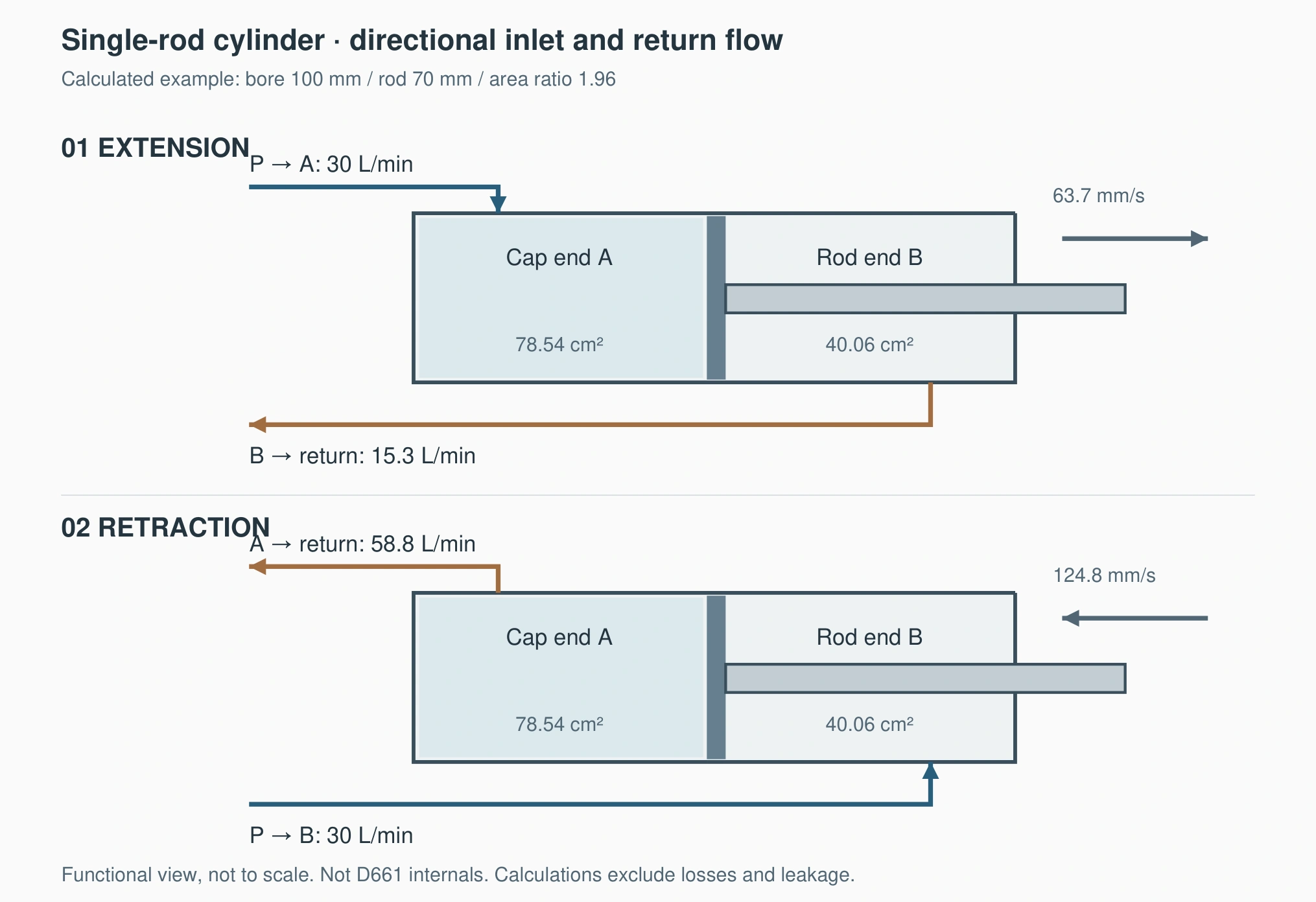
Check the retraction return metering edge, sandwich valves, hoses and filter for approximately 58.8 L/min in this example. Selecting every return component for the pump's 30 L/min can underestimate return-path losses.
Normal low-speed retraction followed by restricted high-speed retraction, accompanied by rising cap-end pressure, makes the return path a specific investigation target. Increasing flow losses can prevent the required speed.
Cap-end backpressure increases the required retraction pressure
Assume a 20 kN retraction resistance and temporarily neglect seal friction. Rod-end pressure must overcome that resistance and the opposing force generated by cap-end pressure.
With cap-end pressure near zero, the ideal rod-end requirement is approximately 49.9 bar. At 10 bar cap-end pressure, it rises to approximately 69.5 bar, an increase of 19.6 bar. The increase follows the 10 bar backpressure and 1.96 area ratio.
Higher return resistance can raise pump pressure while reducing cylinder speed. Additional pressure overcomes discharge resistance, and inadequate supply headroom reduces the differential available at the inlet metering edge.
Use pressure points near the relevant cylinder ports. A low tank-side reading cannot exclude losses between the cylinder and that measuring point.
Spool configuration and actual output affect directional flow
Main-spool position, metering geometry and differential across each edge determine D661 flow. At a fixed opening, throttle flow varies approximately with the square root of differential. Equal opposite electrical commands can therefore produce different working-chamber flows.
An asymmetric spool requires calculation using its specified inlet/return allocation. If directional speeds change after replacement, compare old and new spool allocations and mounting connections. Mounting size and nominal flow alone do not fully identify those configurations.
Directional output limits, ramps and speed conversion also affect controller output. Equal operator settings need to be compared with the actual signals delivered to the valve.
Relate each observation to a specific check
| Machine observation | Relevant record | Items to investigate |
|---|---|---|
| Slow unloaded retraction with high cap-end pressure | Chamber pressures and travel time | Cap-end discharge path and return metering edge |
| Normal unloaded, slow loaded retraction | Supply and chamber pressures at both loads | Retraction force and available metering differential |
| Changed speeds after replacement | Old/new configuration and actual opposite outputs | Spool allocation, connections and output limits |
| Actual output does not match the speed setting | Controller output and available spool feedback | Scaling, drive and valve response |
For a 200 mm stroke, approximately 3.14 seconds extending and 4.81 seconds retracting give average speeds of 63.7 and 41.6 mm/s. The assumed areas imply effective inlet flows of approximately 30 and 10 L/min respectively. Retraction is receiving substantially less flow.
These are average effective chamber flows, excluding total pump losses and pilot consumption. Pressure records help relate the flow difference to return resistance, load or control output.
With limited tools, use existing position indication, travel timing and gauges. Maintain a consistent stroke, comparable temperature and defined load. Qualified personnel should arrange additional measuring points, and existing load-holding measures must remain in place.
For this cylinder, equal inlet flow should give faster retraction. Slow retraction therefore calls for assessing rod-end supply, cap-end return losses and directional control configuration. Inadequate flow, high return pressure and limited output can each reduce speed; valve repair requires the relevant measurement evidence.