Hydraulic Accumulator Nitrogen Charging and Precharge Checks
A hydraulic accumulator stores energy by compressing precharged nitrogen. Before charging, confirm the precharge pressure, reference temperature and gas valve version, then select a compatible charging and gauging unit.
This guide covers accumulators with rechargeable gas valves, focusing on common bladder designs. Check the connection and operating requirements for the specific piston, diaphragm or gas valve version. Charging should be carried out by trained, qualified personnel.
Hydraulic accumulator precharge pressure
Precharge pressure, p₀, is measured with the hydraulic side depressurized and the gas at the specified temperature. During operation, hydraulic fluid compresses the nitrogen, and gas pressure changes with system conditions.
Check the commissioning records, accumulator specifications and charging requirements for the target pressure and reference temperature. The maximum allowable working pressure marked on the shell identifies the vessel's pressure rating. The system design determines the precharge setting.
For energy storage, a common design reference is p₀ at approximately 90% of the minimum working pressure, p₁. For example, if p₁ is 100 bar and the design specifies p₀ = 0.9 × p₁, the precharge is 90 bar at the relevant reference temperature.
This example illustrates the calculation. The actual setting also depends on the model's allowable pressure ratio, temperature range and operating conditions. Shock absorption and pulsation damping use their respective precharge designs.
Nitrogen charging tools and gas valve compatibility
Use dry nitrogen that meets the manufacturer's requirements. Never use oxygen or compressed air. Oxygen in contact with hydraulic oil under high pressure presents a fire and explosion hazard.
Prepare the nitrogen cylinder, pressure regulator, charging hose, charging and gauging unit, and pressure gauge. Each component must be rated for the pressure it can encounter, including cylinder-side pressure. Select a gauge range and accuracy suited to the target precharge.
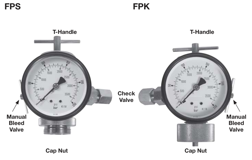
The charging equipment measures pressure, operates the gas valve and vents gas. Identify the gas supply connection, gauge, gas valve operating mechanism and bleed valve before connecting it.
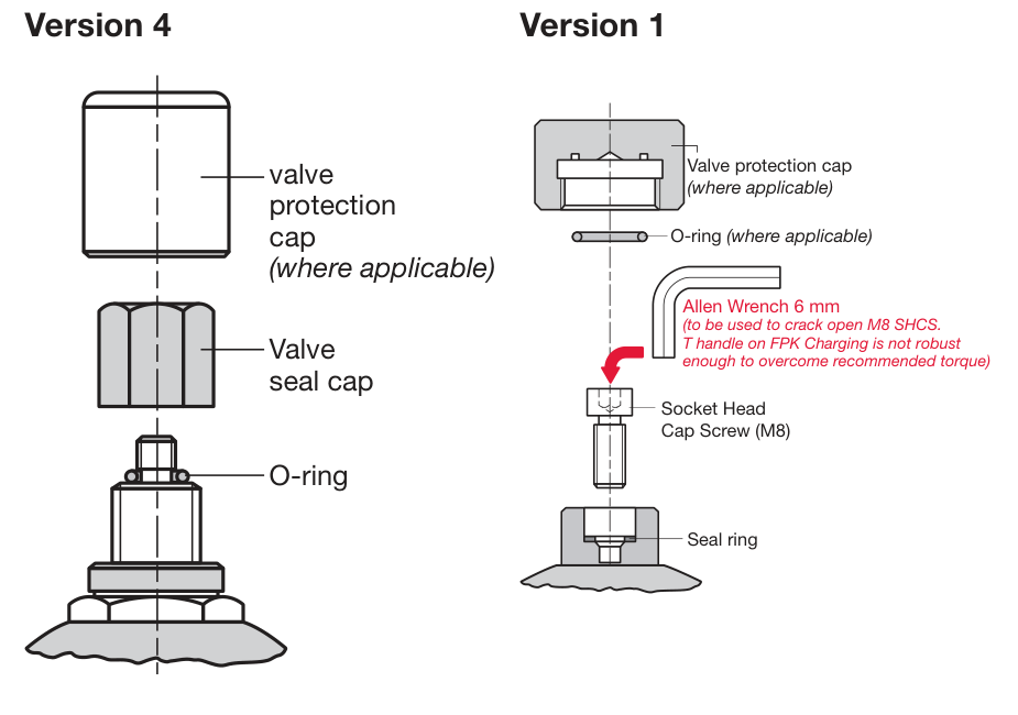
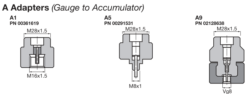
When selecting an adapter, check the threads, sealing arrangement and valve opening mechanism. Once the threads engage, the adapter must also operate the valve correctly and provide a reliable seal. Follow the instructions for the specific tool's handle direction, travel and tightening torque.
Keep the gas supply closed and place the tool in its specified initial position before connecting. Inspect hoses, fittings and seals, and replace damaged parts first.
Isolate and depressurize the hydraulic side
An accumulator can retain pressurized fluid after the pump stops. Before charging or checking precharge, follow the equipment's maintenance procedure to isolate power and pressure sources, prevent unexpected startup and isolate the accumulator from the hydraulic system.
Release hydraulic pressure through the designated depressurization path and confirm that the accumulator branch is depressurized. Include sections isolated by check valves, shut-off valves or other components. Never loosen a hydraulic fitting to test for residual pressure.
The gas side can retain high-pressure nitrogen after hydraulic pressure reaches zero. Keep the gas valve body and accumulator shell connections intact during precharge checks. Disassembly requires the separate depressurization and maintenance procedure for that model.
Accumulator nitrogen charging sequence
-
Confirm and record. Check the model, gas valve version, target pressure and reference temperature. Complete hydraulic-side isolation and depressurization, and record the measurement temperature.
-
Connect the gauging unit. Keep the gas supply closed and the tool in its specified initial position. Connect the unit and open the accumulator gas valve as instructed so the gauge communicates with the gas side, then record the existing gas pressure. If the pointer remains stationary, check the connection and tool operation first.
-
Charge slowly. Control the gas supply through the regulator and charging equipment, introducing nitrogen slowly. Take particular care during initial charging or after bladder replacement. Rapid charging can damage the bladder.
-
Recheck after stabilization. Stop the gas supply and allow the temperature to stabilize for the time specified for the model. Take another reading with the gas side correctly connected to the gauging unit. Make small adjustments based on the stabilized pressure.
-
Close the valves, vent the tool and disconnect. After reaching the target and rechecking, close the nitrogen supply and the accumulator gas valve as instructed. Use the tool's bleed valve to release residual pressure from the gauging unit and associated lines. Confirm that the equipment is depressurized before disconnecting. Check the gas valve seal and refit the specified sealing and protective caps.
Closing the accumulator gas valve before removing the tool retains the precharged nitrogen. Opening the tool's bleed valve afterward releases tool-side pressure. Complete these actions in that order.
Keep the venting area well ventilated and personnel clear of the discharge direction. Nitrogen accumulation in an enclosed space can reduce the oxygen concentration.
Pressure changes and abnormal readings
Gas temperature and line pressure affect gauge readings during charging. Assess precharge using the reading taken after the gas supply has stopped and the temperature has stabilized. Use the specified stabilization time for initial charging, charging after maintenance or routine adjustment.
| Observation | Checks |
|---|---|
| Pressure rises during charging and changes after the supply stops | Communication between the gas side and gauging unit; temperature stabilization |
| Repeated significant pressure loss at the same temperature | Gas valve sealing, tool connections and internal condition |
| Oil appears at the gas valve | Stop charging and inspect the separator and seals under the maintenance procedure |
| Pressure drops again soon after topping up | Identify the cause of pressure loss before proceeding |
If cylinder pressure is below the charging requirement, check the available gas pressure and regulator, then follow the specified charging plan. A zero reading, oil at the gas valve or abnormal pressure loss requires a pause in routine topping-up. Check the gauging equipment first, then have qualified personnel inspect the accumulator.
Topping up and charging after maintenance
Routine topping-up restores precharge to the specified setting after confirming that the accumulator is in serviceable condition and the hydraulic side is isolated and depressurized. Charging after bladder replacement also requires the model's assembly checks and initial charging preparation.
Some diaphragm accumulators have factory-sealed gas ports and a factory-set precharge. Confirm whether the gas port permits recharging before attempting an adjustment.
Record the model, target precharge and reference temperature, actual measurement temperature, stabilized pressure, inspection date and seal check results. Return the system to service under the equipment's recommissioning procedure. Use the same measurement conditions for subsequent checks to make pressure changes comparable.
For model selection, view the hydraulic accumulator range. For help checking gas valve connections and configuration, contact Yikuang Hydraulic with the complete model number and nameplate details.