HYDAC SB330: How Much Oil Can a 5 L Accumulator Deliver?
A machine may run out of pressure before an action finishes even after a 5 L accumulator is fitted. Capacity calculations can explain why: nitrogen occupies part of the vessel throughout operation, and usable oil delivery depends on pre-charge and the operating-pressure range.
We use SB330-5A1/112A9-330A to explain the model and an illustrative 100–160 bar duty. Model information follows HYDAC's European 2024 catalogue; the calculation assumes an effective gas volume of 5 L.
SB330-5A1/112A9-330A model breakdown
| Field | Meaning | Selection detail |
|---|---|---|
| SB330 | Bladder accumulator series | Series configuration and nameplate |
| 5 | Nominal capacity, 5 L | Use actual effective gas volume for sizing |
| A | Standard threaded fluid connection, internal sealing face | Matching connection and seal |
| 1 | Standard gas connection | Compatible checking and charging equipment |
| 112 | Carbon-steel fluid port and shell, NBR bladder | Fluid and temperature compatibility |
| A9 | China-related approval code | Delivered certification |
| 330 | Permissible operating-pressure code, bar | Nameplate and temperature conditions |
| Final A | ISO 228 BSP fluid-thread code | Thread size and assembly drawing |
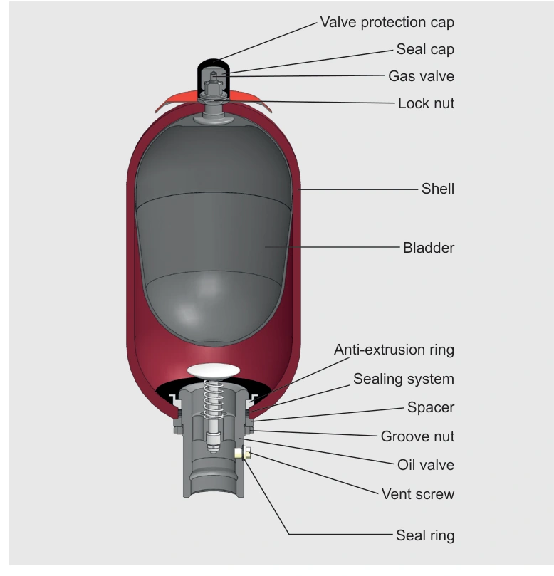
Pre-charge is selected for the duty. Energy storage, pulsation damping and shock absorption have different requirements. The 330 bar code identifies the relevant pressure configuration. Use the assembly drawing for this 5 L unit's dimensions and connections.
Approximately 1.68 L between 100 and 160 bar
Assume an effective gas volume of 5 L, pre-charge of 90 bar, minimum operating pressure of 100 bar and maximum of 160 bar, all gauge pressures. Use a slow, approximately isothermal process and assume atmospheric pressure is 1 bar.
Absolute pressures are therefore 91, 101 and 161 bar. Gas volume at 100 bar gauge is approximately 5 × 91 / 101 = 4.50 L; at 160 bar it is approximately 5 × 91 / 161 = 2.83 L.
Discharging from 160 to 100 bar releases approximately 1.68 L of oil. For actual sizing, replace the assumed 5 L with the assembly's effective gas volume.
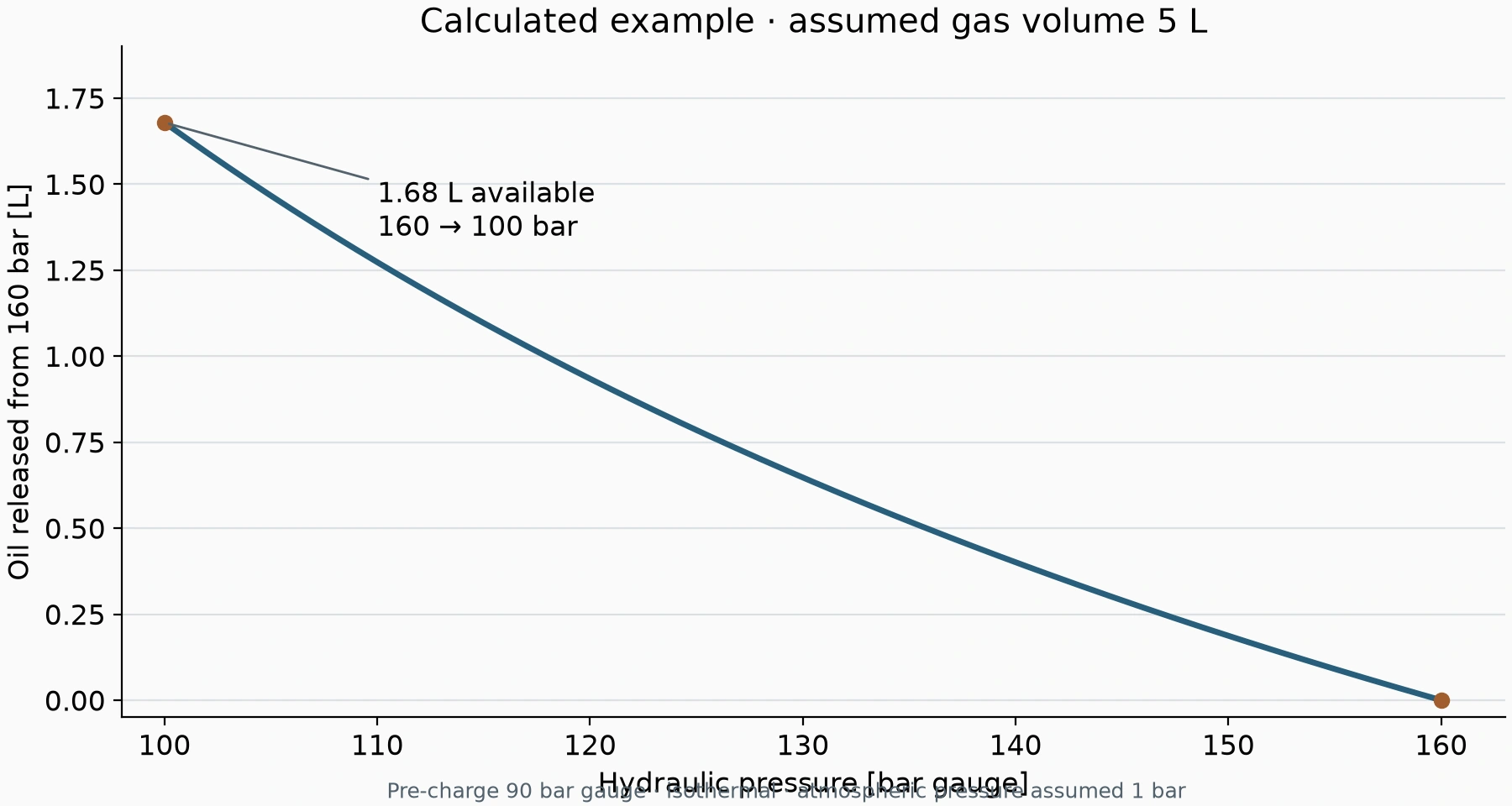
If the machine needs 3 L within that range, theoretical delivery is already insufficient. Increase capacity or reassess the pressure-range design. A 1 L demand still requires discharge-rate, thermal and pressure-loss checks, especially for a fast action.
A changed duty can exceed the same accumulator's capacity
For example, extending a clamp's holding time increases oil consumed by continuing internal leakage. A healthy accumulator can reach minimum pressure sooner in the longer cycle.
A faster action requires the same oil volume in less time, increasing pressure loss through pipes and valve blocks. Pressure may remain at the accumulator while pressure at the actuator falls below the requirement. Compare both pressures during motion.
If duty is unchanged but holding time deteriorates, investigate leakage and pre-charge. Qualified personnel should check pre-charge with compatible equipment after the hydraulic side has been isolated and depressurised.
Select pre-charge for the duty and temperature
Catalogue constraints include p0 ≤ 0.9 p1 and a usual maximum p2:p0 ratio of 4:1. Within these limits, select pre-charge for the operating pressures, temperature and discharge process.
Use the specified nitrogen medium. Record both pre-charge and measurement temperature so later checks can be compared meaningfully.
For this example, an assumed 5 L effective gas volume provides about 1.68 L of usable oil. Compare that delivery with required oil volume, discharge time and minimum operating pressure.