HYDAC SAF: Selecting Isolation and Discharge Functions
An accumulator needs a way to be isolated from the hydraulic system and its stored hydraulic pressure released for maintenance. HYDAC SAF combines isolation, discharge and pressure limitation in one block.
Selection depends on normal flow, the maintenance discharge path, the discharge valve's de-energised state and required protective-branch flow. This article follows HYDAC's European 2024 catalogue.
S connects to the accumulator, P to the system and T to return
The shut-off valve is in the main S-to-P path. The discharge branch leads to T, which requires the specified separate, low-pressure return connection.
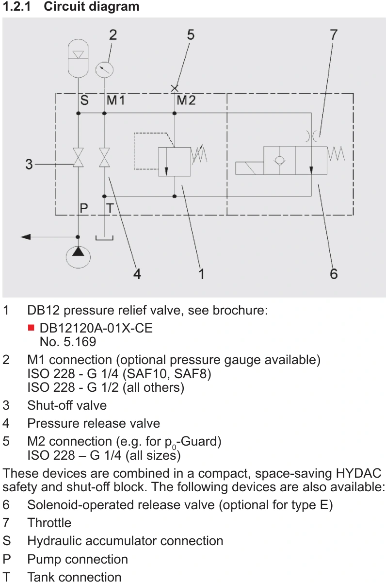
After pump shutdown and isolation, system pressure may fall while pressure remains at the accumulator. A gauge at P then measures the system side only. Check accumulator-side pressure at the designated measuring point.
The pressure-limiting valve discharges under its opening conditions and closes as pressure falls below them. Maintenance discharge uses the applicable release path. Qualified personnel must follow the machine's procedure and verify pressure release.
Select M for manual discharge; distinguish Y and Z for solenoid functions
M provides manual discharge. E provides a solenoid discharge arrangement, whose normally open or normally closed function determines its de-energised state.
| Configuration | Function | Application check |
|---|---|---|
| M | Manual discharge | Personnel perform maintenance discharge under procedure |
| E with Y function | Normally open solenoid discharge | Verify required release behaviour on power loss |
| E with Z function | Normally closed solenoid discharge | Verify energised discharge behaviour |
| T return | Discharged oil returns to tank | Unobstructed path and permitted backpressure |
Suppose a machine requires hydraulic accumulator pressure to be released on loss of power. The selected discharge circuit must provide that state. A normally closed branch remains closed when de-energised; the E designation alone does not establish power-loss discharge.
Another machine may need stored energy to preserve a function during a brief interruption. The machine designer must establish the required state, select the corresponding Y or Z function and retain the necessary maintenance discharge provisions.
Respect the lowest applicable assembly pressure rating
The referenced SAF family includes a maximum operating-pressure rating of 400 bar. When combined with a 330 bar accumulator, allowable operation is also constrained by the accumulator, hoses and fittings. A lower-rated component further limits the assembly.
Select the pressure-limiting setting within those ratings and applicable requirements. Specify the setting and configuration when ordering, then verify the function during acceptance.
Check main-path and protective-branch flows separately
During short-term accumulator delivery, main-path pressure loss reduces pressure reaching the actuator. Restrictive connections can leave adequate accumulator pressure but insufficient actuator performance.
For overpressure protection, assess the oil that must be discharged. If a relevant condition allows the pump to continue supplying the protected volume, size the pressure-limiting branch for the applicable maximum inflow. Main-path capacity does not establish relief-valve discharge capacity.
Information to provide when ordering
| Item | Required information |
|---|---|
| Accumulator | Complete model, allowable pressure and connection dimensions |
| Normal operation | Flow, short-term oil delivery and permissible pressure loss |
| Pressure limitation | Setting and applicable protective flow duty |
| Discharge | M/E arrangement, Y/Z function and solenoid voltage |
| Installation | S/P/T connections, measuring ports, clearance and return path |
Select SAF for the required supply, isolation, discharge and de-energised behaviour. Pressure rating and connections establish compatibility; discharge configuration and branch capacities establish the required functions.