EMG SV1 Guides in the Wrong Direction after Replacement
If strip deviation increases when automatic guiding is engaged after an SV1 replacement, leave automatic guiding and control the mechanism under the machine procedure. Establish direction before adjusting gain or dither. Lower gain may slow the error's growth without restoring correct feedback.
Separate three relationships: command to mechanism movement, mechanism movement to strip response, and strip position to sensor indication. Their combined effect establishes the loop direction.
Define the viewing position and positive direction
Left and right reverse when viewed from opposite ends of a machine. Fix the observation point, identify movement using machine coordinates or drawings, and record which physical strip direction increases the sensor position value. A note saying only “reversed” is incomplete.
Keep valve ports A/B, cylinder extension/retraction and strip movement separate. Whether A supplies the cap or rod end depends on the connections. Whether extension moves the strip left or right depends on the mechanism. The valve designation cannot define machine left and right.
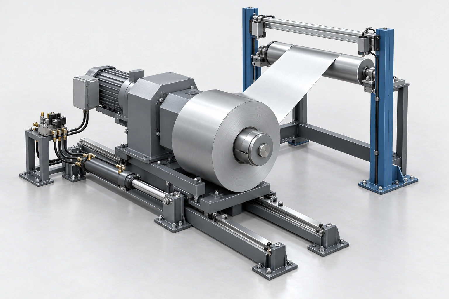
EMG's uncoiler application description also identifies transport delay with downstream sensing. A sensor may not yet have seen the affected strip immediately after a small movement. No immediate change does not establish reversed direction. Observation time must follow the sensing arrangement, strip speed and machine commissioning procedure.
Compare command-to-movement behaviour with the original record
Maintenance should start with the original wiring, commissioning settings and controlled movement records. Within the approved commissioning mode and safe travel, compare the directional command, actual current direction and mechanism movement. Repeatedly engaging automatic guiding is not a suitable direction test.
If the same command and current direction now produce the opposite mechanism movement, the change lies in the current-to-mechanism path. Check actual wiring, the valve variant, mounting interface and A/B connections.
If the command is unchanged but actual current direction has reversed compared with the original record, investigate drive polarity and wiring first. This moves the investigation upstream without first disturbing hydraulic lines.
Also match flow grade, pressure version, overlap and drive connection to the original configuration. Changed response affects speed and stability, but persistent correction in the wrong direction requires a sign check before a flow-based explanation.
Correct manual movement does not establish correct automatic feedback
If command-to-mechanism behaviour matches the original record, check sensor coordinates, reference position and automatic control direction. Reversed sensor installation, a changed coordinate configuration or a controller direction parameter can alter the feedback sign.
The commissioning objective is specific: corrective movement should bring actual position toward the reference and reduce the absolute deviation. Interpretation must allow for transport delay, tension and mechanism response rather than treating a delayed instant as the final trend.
For example, define position as increasing to the right, error as reference minus measured position, and positive output as increasing measured position. With a reference of 0 mm and measurement of +3 mm, the error is −3 mm. Correct action should reduce measured position toward zero.
If the movement instead drives the measurement to +4 and +5 mm, absolute deviation increases and this loop direction is wrong. These signs are definitions for the example. A machine display may define error the other way around, so establish its convention first.
| Comparison | Priority check |
|---|---|
| Same command, opposite actual current direction | Drive polarity, settings and wiring |
| Same actual current direction, opposite mechanism movement | Current-to-mechanism path, valve configuration and A/B connections |
| Command-to-mechanism relationship unchanged, position indication reversed | Sensor orientation, coordinates and calibration |
| Those relationships unchanged, automatic correction still wrong | Reference, error definition and controller direction configuration |
Why swapping wires or A/B lines is not the first correction
Reversing electrical direction or exchanging A/B connections can change movement direction, but whether either method is acceptable depends on the machine drawing, drive connection and safety functions. Correct the section that has been shown to differ from the design.
Counterbalance valves, pilot-operated checks and other branch functions may depend on their association with the load. Exchanging A/B lines changes that relationship. P and T must not be interchanged to correct guiding direction. Electrical changes must likewise follow the specified polarity configuration or wiring rather than trial energisation of connector pins.
Changing both sensor direction and drive direction can produce two reversals that cancel in automatic operation. The strip may centre while manual direction, limits or diagnostic coordinates still disagree with the design. Change one established item at a time, preserve the original setting and verify bidirectional operation and limiting functions as specified.
A hypothetical replacement example
Assume the original commissioning record shows a particular command producing positive current and movement in the designated positive machine direction. After an SV1 replacement and reconnection, the same command produces negative current and opposite movement. Sensor coordinates and hydraulic routing are unchanged.
These records prioritise changed drive direction or wiring. Suppose maintenance identifies an altered drive-polarity setting, restores it from the record and verifies that command, current, mechanism direction and sensor response again correspond. Automatic guiding is checked only afterward under the commissioning procedure.
That before-and-after record supports the changed drive-polarity diagnosis. If actual current direction already matches the original record, continue with the mechanism and feedback chain.
Leave automatic guiding first, then compare command, current, mechanism movement and sensor indication with the original records. Correct the relationship that changed. Once direction is verified, adjust speed and gain and recheck bidirectional operation, limits and automatic recentring.