EMG SV1 Moves in One Direction Only: A Diagnostic Sequence
When guiding works in one direction but not the other, identify where the two action chains begin to differ. Check whether the reverse command exists, whether actual current follows it, and then whether the corresponding hydraulic and load paths respond. This separates control-side problems from hydraulic-side problems.
First exclude a legitimate limit or interlock. A prohibited direction at an end position may be correct machine protection. Do not bypass an interlock to test the valve.
Start with movement permission and position
Use existing indications for limits, emergency stops, drive enable, sensor validity and alarms. Establish whether the affected direction is permitted, whether the mechanism is at the end of travel, and whether the observation concerns automatic guiding or an established manual mode.
If automatic guiding works in one direction only but an authorised, controlled bidirectional check works both ways, the execution chain has demonstrated bidirectional movement capability. Investigate deviation input, directional limits and automatic logic before removing the valve.
Movement in both directions does not establish full performance under every load. Compare the operating conditions in which the fault occurs; pressure and flow requirements can differ with load and opening.
Compare commands, then actual coil current
If there is no output command for the affected direction, investigate the sensor, logic and enable chain. The valve has not yet received a movement request, so this observation does not establish a stuck valve.
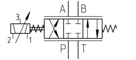
If both required commands exist, maintenance should check actual current using the applicable wiring and measurement method. The SV1 electromagnetic rotary drive requires the version-specific bidirectional current arrangement. Two movement directions do not necessarily mean two separate switching coils. Do not energise it as though it were an ordinary on/off directional valve.
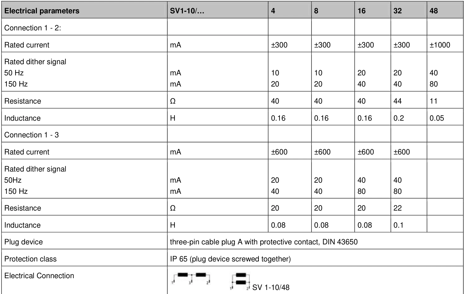
Rated current also depends on the connection. For grades 4 through 32 in the retained DB_SV1-10_05_en, connection 1–2 is listed at ±300 mA and connection 1–3 at ±600 mA. Establish the actual arrangement from the applicable identification, wiring and drive settings. The same current cannot be assumed equivalent across connections.
With matching settings and connections, normal current in one direction but inadequate current in the other puts drive-output limits, power and wiring first. If only a monitoring value appears abnormal, verify that measurement before treating it as actual output loss.
With current established, follow the hydraulic response
Once maintenance confirms that actual current meets the affected movement's requirement, compare P, T, A and B measurements during that movement. One direction supplies one work port while allowing the opposite side to return; the reverse direction exchanges the paths. Restriction in either supply or return can prevent movement.
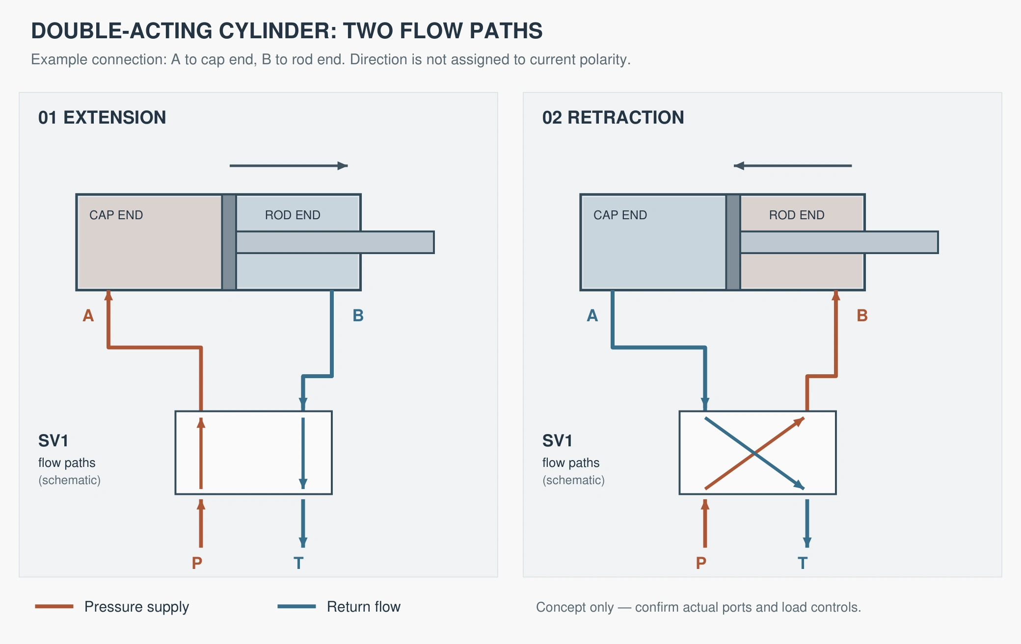
Reversing movement makes the previous supply side the return side. A restriction on that side can therefore become apparent in the opposite direction. Trace supply and return separately to locate the next check, rather than examining the command alone.
If supply at P near the valve remains stable but the intended work-port pressure does not respond, inspect the metering path, manifold and relevant work-port connection against the circuit. This prioritises the supply-to-work-port section without automatically proving valve damage.
If work-port pressure rises near its limiting setting but the mechanism remains stationary, stop holding an increasing command. Check load, mechanical obstruction, opposite-side return and the opening conditions of load-holding components. Opposing pressure reduces net cylinder force; high inlet pressure alone does not establish sufficient usable force.
A single-rod cylinder has unequal effective areas. Equal pressure and inlet flow produce different force and speed in its two directions. Load direction, counterbalance valves and pilot-operated checks add their own conditions. Normal movement one way does not eliminate those components from the investigation.
| Observed difference | Investigation starts with |
|---|---|
| Direction not permitted or travel limit active | Machine state, interlocks and position |
| Permission present but no output command | Sensor, logic and output limits |
| Command present but required actual current absent | Drive, power, wiring and current measurement |
| Current established and P normal, intended work-port pressure absent | Valve, manifold and branch supply path |
| Work-port pressure rises but movement is absent | Opposing return pressure, holding valves, load and mechanical resistance |
The table identifies the next section to investigate. Pressurised measurements, isolation and dismantling belong to maintenance using the machine procedure. Operators should not disconnect lines, plug ports or force manual overrides for verification.
A hypothetical reverse-current limit
Assume an SV1-10/16 installation uses connection 1–2. Its commissioning record specifies +120 and −120 mA for this comparison movement, with the mechanism in a permitted mid-travel region.
Both directional requests are present. Measured current is approximately +120 mA in the working direction but only −12 mA in the failed direction. The next investigation is the drive chain, without immediately sending the valve for repair.
Suppose maintenance then finds an incorrectly low negative-current limit in the driver. Restoring the recorded setting restores actual negative current and reverse movement under the same conditions. That before-and-after verification supports the output-limit diagnosis.
If reverse current was already correct, this conclusion does not apply. Continue with work-port pressure, return flow and load. The evidence determines which section needs correction.
Check permission, command, actual current, work-port pressure and load in that order. Restore a missing upstream condition before judging downstream components. With normal current established, follow the hydraulic paths. This separates control and drive problems from valve and actuator problems.