EMG SV1 Abrupt Motion at Small Commands: Current, Starting Resistance and Lost Motion
A small correction makes the roller frame jump. After reversal the strip moves back, then overshoots to the other side. Distinguish a large current delivered immediately from output that accumulates while the mechanism remains stationary and then starts suddenly.
The first pattern calls for drive-scaling checks. The second calls for starting-resistance and center-flow checks. Cylinder movement without frame movement points to the mechanical connection.
The same 10% command can produce twice the current
For the 16 L/min version in OEM sheet DB_SV1-10_05_en, connection 1–2 is rated at ±300 mA and connection 1–3 at ±600 mA. Connection and driver current range must match; SV1 connection and rated-current table explains the connection-specific ratings.
Assume connection 1–2 with a ±300 mA range: a positive 10% command gives 30 mA. Keeping that connection but incorrectly changing the range to ±600 mA gives 60 mA at the same 10%.
The display still reads 10%, but main current has doubled. The outer controller has not increased its command; the percentage-to-current conversion changed in the driver.
This calculation compares linear main-current scaling without bias or dither. Twice the current does not establish twice the cylinder speed: center characteristics, pressure drop and load affect flow.
If abrupt motion follows driver replacement, parameter restoration or rewiring, compare old and new ranges and measured currents. Electrical personnel should use a supported monitor output or suitable current measurement device, not arbitrarily connect a meter across the output.
Output rises while the frame remains stationary
Assume correction output increases gradually but the frame does not move. Once cylinder force exceeds static friction, motion starts. Lower moving resistance then makes the accumulated output excessive, producing a sudden movement.
Examine the stationary interval. Rising main current and cylinder driving differential with unchanged position call attention to starting resistance. Dry guides, seal friction and misaligned loading can contribute.
A controller with integral action may continue accumulating output while the strip error remains. That accumulation does not disappear immediately at startup and can increase overshoot. Separate tuning from mechanical repair rather than increasing gain to force motion through binding.
Inspect and lubricate only after stopping and isolation, with automatic guiding disabled while handling guides, pins or joints.
The cylinder moves before the frame
During reversal, the rod or linkage moves but the frame pauses before following. Before clearance is taken up, cylinder movement is not fully transmitted to the frame.
Observe rod, connecting pin and frame during the same small reversal. Continuous cylinder position with lost frame motion calls for pin, joint and transmission-clearance checks. Cylinder feedback alone misses that interval.
Use the approved maintenance mode and never put a hand on a moving joint to feel clearance.
A 6% overlap code is not a 6% startup command
The difference between 1% and 6% overlap near center appears mainly in flow near center. With insufficient initial flow, the controller may keep increasing output; movement becomes more pronounced after the opening region is reached.
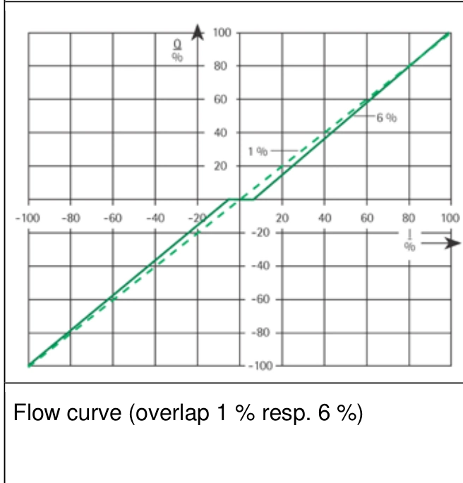
The horizontal axis is rated-current percentage I/IN and the vertical axis is flow percentage Q/QN. Near-center differences show how overlap changes flow at small current; the graph does not directly specify cylinder startup.
The /6 in SV1-10/16/315/6 identifies the overlap version. It does not establish cylinder startup at exactly 6% controller command. Current scale, bias, metering pressure drop and load also determine startup.
A different overlap or larger-flow valve changes the original circuit's regulating behavior. Neither removes incorrect current scaling or mechanical lost motion.
What dither and gain can change
Dither adds a periodic disturbance to main current to improve small-signal motion conditions. It does not remove linkage clearance or repair binding guides. The OEM table does not explicitly identify peak, peak-to-peak or RMS amplitude, so its mA entries cannot simply be entered as a driver percentage.
Lower outer-loop gain weakens correction but may also slow it. After adjustment, check recovery to setpoint at the same strip speed and disturbance. Less abrupt motion alone does not establish retained guiding capability.
Record three different patterns
| Observed pattern | Compare | Investigate |
|---|---|---|
| Small command immediately gives more current than before | Old and new main current at the same percentage | Driver range, bias and connection |
| Current rises while stationary, followed by sudden startup | Main current, driving differential and mechanism position | Starting resistance, center flow and control accumulation |
| Cylinder reverses before the frame moves | Rod, joints and frame position | Mechanical clearance and connections |
All three can feel like excessive movement at a small command, but their remedies differ. Identify where the change begins to distinguish driver correction, mechanical repair and interaction between control and valve center behavior. For continued reversals and sustained oscillation, compare sensor and actuator delay checks.