EMG SV1-10 Drive Current and Dither: Connections and Replacement Checks
Select an EMG SV1-10 driver by flow version and electrical connection. In the cited manufacturer table, the 4–32 L/min versions use ±300 mA with connection 1–2 and ±600 mA with connection 1–3. The 48 L/min version lists ±1000 mA for connection 1–2. A common series name does not establish a common drive current.
Dither is a periodic perturbation superimposed on the control current to improve small-signal movement conditions. It serves a different purpose from the main command. Driver output, superimposed signal and limits must work together; increasing dither alone does not resolve every breakaway problem.
This article uses manufacturer data sheet DB_SV1-10_05_en, document ID EMGDES-00002822. Values apply to that documented version. Check the nameplate, original wiring and corresponding driver documentation when replacing an older valve.
Rated Current Changes with Connection
| Flow version | 1–2 rated current | 1–2 resistance | 1–3 rated current | 1–3 resistance |
|---|---|---|---|---|
| 4 L/min | ±300 mA | 40 Ω | ±600 mA | 20 Ω |
| 8 L/min | ±300 mA | 40 Ω | ±600 mA | 20 Ω |
| 16 L/min | ±300 mA | 40 Ω | ±600 mA | 20 Ω |
| 32 L/min | ±300 mA | 44 Ω | ±600 mA | 22 Ω |
| 48 L/min | ±1000 mA | 11 Ω | Not listed | Not listed |
The designations 1–2 and 1–3 come from the original table and must be interpreted with the wiring drawing. Do not infer terminals from connector appearance. The 48 version has a separate connection illustration; its blank 1–3 column does not support extrapolating another connection or current rating.
Assume an existing 16 L/min valve uses connection 1–3. A replacement driver limited to ±300 mA does not meet the table's ±600 mA rated-drive requirement. Conversely, connection 1–2 should not simply retain a ±600 mA limit. Establish connection and current range together before adjusting control settings.
For example, assume the original 16 L/min version uses connection 1–3 and the controller displays a 50% command. With a linear ±600 mA driver range, positive half-scale gives +300 mA. Changing the range to ±300 mA gives only +150 mA at the same displayed percentage. This comparison excludes offset, dither and limiting, and considers only main-command scaling.
This establishes rated-drive compatibility, not a prediction that insufficient current halves flow. Overlap, pressure drop, magnetic behaviour and load affect actual output.
Check Driver Capacity Separately for the 48 Version
Changing from the 32 to the 48 version changes the connection 1–2 rating from ±300 to ±1000 mA and resistance from 44 to 11 Ω. A driver suitable for the 32 version is not automatically capable of driving the 48 version to its rated condition.
Resistance alone also does not determine supply voltage. Static I×R estimates resistive voltage drop; changing current additionally involves inductance, driver losses and cable effects. Check permitted load, output current and dynamic requirements against the driver's documentation rather than treating the valve coil as an ordinary voltage load.
Now assume a machine uses the 32 version, connection 1–2, with a driver limited to ±300 mA, and a 48 version is proposed. That driver cannot reach the replacement valve's listed ±1000 mA rated current, so the existing electrical arrangement is not a rated match. Verify or replace the driver before checking flow at the actual pressure drop. Increasing gain cannot create output capacity the driver does not have.
Select Dither by Frequency, Flow Version and Connection
| Flow version | 1–2: 50 Hz | 1–2: 150 Hz | 1–3: 50 Hz | 1–3: 150 Hz |
|---|---|---|---|---|
| 4, 8 L/min | 10 mA | 20 mA | 20 mA | 40 mA |
| 16, 32 L/min | 20 mA | 40 mA | 40 mA | 80 mA |
| 48 L/min | 40 mA | 80 mA | Not listed | Not listed |
The table provides separate 50 and 150 Hz conditions; it does not instruct simultaneous superposition of both frequencies. Values are in mA. If the driver displays a percentage, establish the current used as its reference.
The table does not specify whether these figures are peak, peak-to-peak or RMS. Do not directly equate its 20 mA with a driver's identically labelled setting or an assumed percentage. Check the corresponding amplifier's dither definition first.
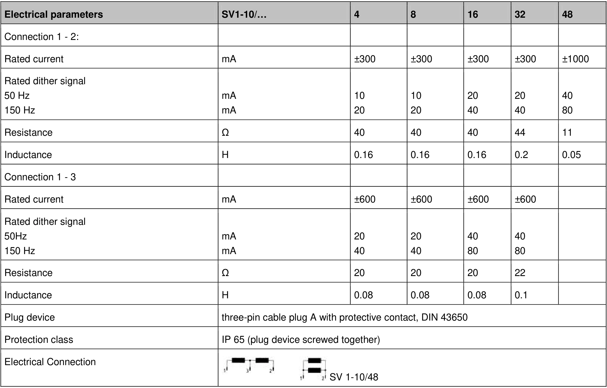
For the 16 version with connection 1–2, the listed 150 Hz dither value is 40 mA. Only if the driver explicitly uses 300 mA as its percentage reference and the amplitude definitions agree does 40÷300×100% correspond to approximately 13.3%. With a 600 mA reference, the same 40 mA corresponds to approximately 6.7%. These illustrate conversion only; do not enter either setting before verifying the amplitude definition.
A Guiding-System Replacement Example
Assume a guiding system uses the 16 L/min SV1-10 version, connection 1–2 and 150 Hz dither. The cited table calls for checking a ±300 mA rated current and a 40 mA listed dither value. This is an assumed configuration, not a field commissioning record.
If small-command movement becomes delayed after replacement, compare old and new output ranges, limits, connections and dither definitions first. Using the 20 mA value from the 50 Hz row does not establish equivalence with the original 150 Hz configuration. That mismatch alone, however, does not prove the sole cause of delayed motion.
First verify that actual output current matches the settings. Then compare breakaway and reversal at comparable oil temperature, pressure drop and load. If current is correct but the mechanism still hesitates, continue with overlap, cylinder friction and hydraulic conditions.
Record Both the Main Command and Superimposed Signal
With dither, instantaneous current varies around the main command. An average reading does not fully describe frequency, amplitude or clipping. When evaluating dither, use current monitoring suitable for the driver circuit and examine the waveform in accordance with equipment measurement requirements.
Near output limits, check whether the combined main command and dither are being limited. Continuous, peak and superposition capabilities come from driver documentation. The table's rated current is not permission for arbitrary peak overshoot.
Record the full valve model, connection, driver model, output range, dither frequency and amplitude definition. These details support a defensible distinction between electrical mismatch and hydraulic actuation problems, and provide a usable replacement record.
Summary
Start SV1-10 drive selection with flow version and connection. In the cited table, 4–32 L/min versions use ±300 mA for 1–2 or ±600 mA for 1–3. The 48 version lists ±1000 mA for 1–2 and requires separate settings.
Then match dither frequency, connection and flow version to the driver's amplitude definition. Establish electrical compatibility before evaluating breakaway, reversal and fine correction, so any adjustment follows evidence.