EMG SV1 vs SV2: Selecting Single-Stage and Two-Stage Servo Valves
EMG SV1 controls working flow through a single-stage valve. SV2 uses a pilot valve to actuate a main stage. For greater flow requirements, evaluate SV2 together with its pilot supply and return, main-spool feedback and amplifier.
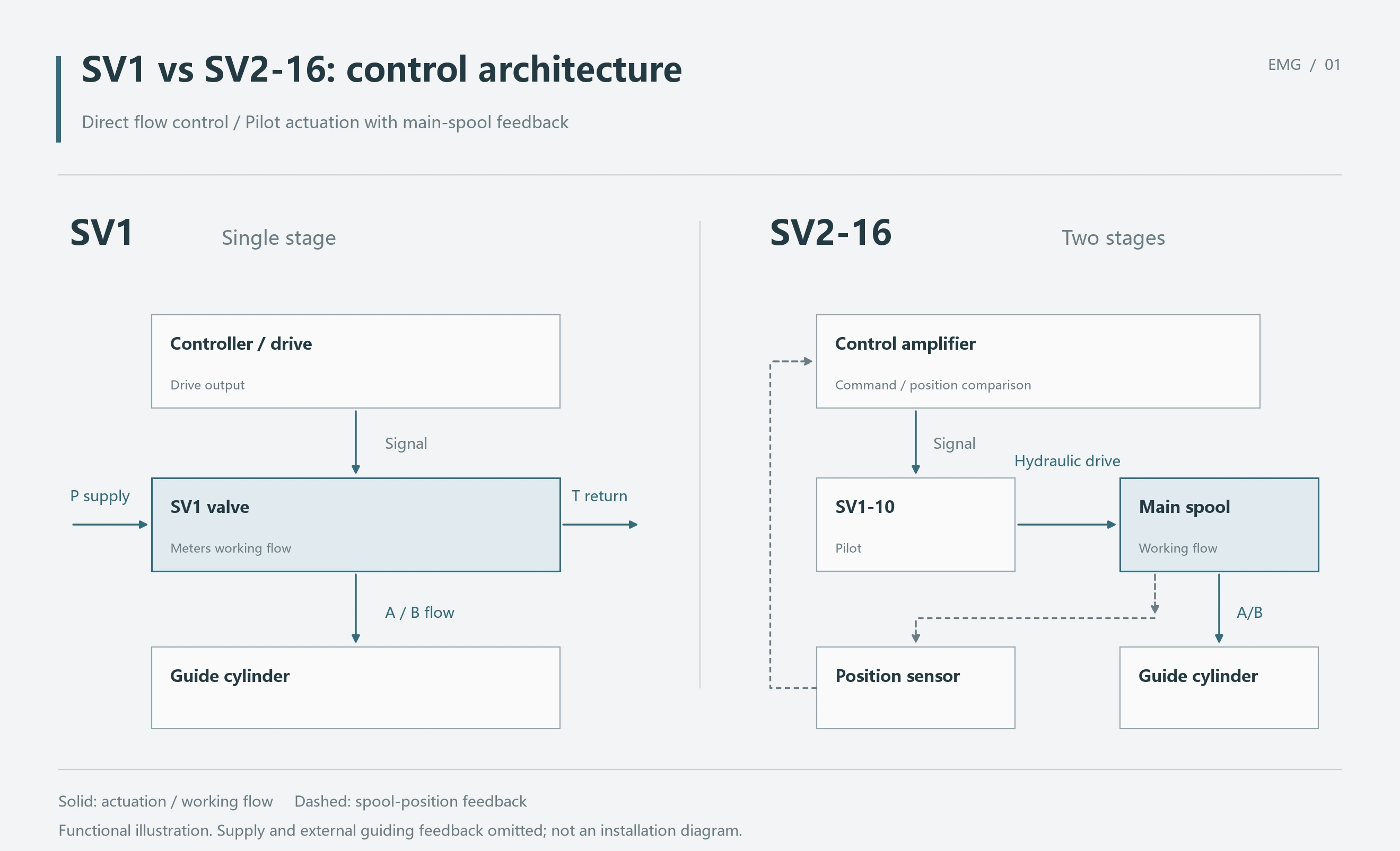
SV2-16, for example, uses an SV1-10 pilot, a main spool valve and an inductive position transducer. The SV1-10 actuates the main stage, while the main spool meters working flow to the cylinder. Moving from SV1 to SV2 changes the hydraulic and control arrangement as a whole.
SV2 Adds a Main Stage and Position Feedback
The SV1-10 pilot on the SV2-16 manifold hydraulically moves the main spool, controlling flow to working ports A and B. An inductive transducer measures main-spool position and returns the actual value to the control amplifier.
The amplifier compares command and feedback, then adjusts pilot output to position the main spool. Assessing SV2 operation therefore requires checking both pilot output and main-stage tracking. Testing the pilot alone does not verify the main-spool position loop.
| Comparison | SV1 single-stage arrangement | SV2 two-stage arrangement, illustrated by SV2-16 |
|---|---|---|
| Working-flow control | Directly by the single-stage valve | By the main spool valve |
| SV1-10 function | Can operate independently for flow control | Acts as the pilot for the main stage |
| Main-stage position feedback | No separate second hydraulic stage | Inductive position transducer |
| Control matching | Corresponding drive and controller | Pilot drive, main-stage feedback and amplifier inner loop |
| Replacement scope | Complete model and original assembly | Main stage, pilot, transducer and controller as a matched arrangement |
Recalculate the Operating Point When Flow Demand Increases
Assume a cylinder has an effective area of 40 cm² in one direction. At 0.1 m/s, supply demand is 24 L/min; increasing speed to 0.25 m/s raises demand to 60 L/min. Calculate return flow separately using the effective area on the opposite side.
An existing manufacturer data sheet for SV1-10 lists rated flows of 4, 8, 16, 32 and 48 L/min at 20 bar rated valve pressure drop. The following comparison uses that edition's SV1-10 data and does not establish the flow limit of the entire SV1 family.
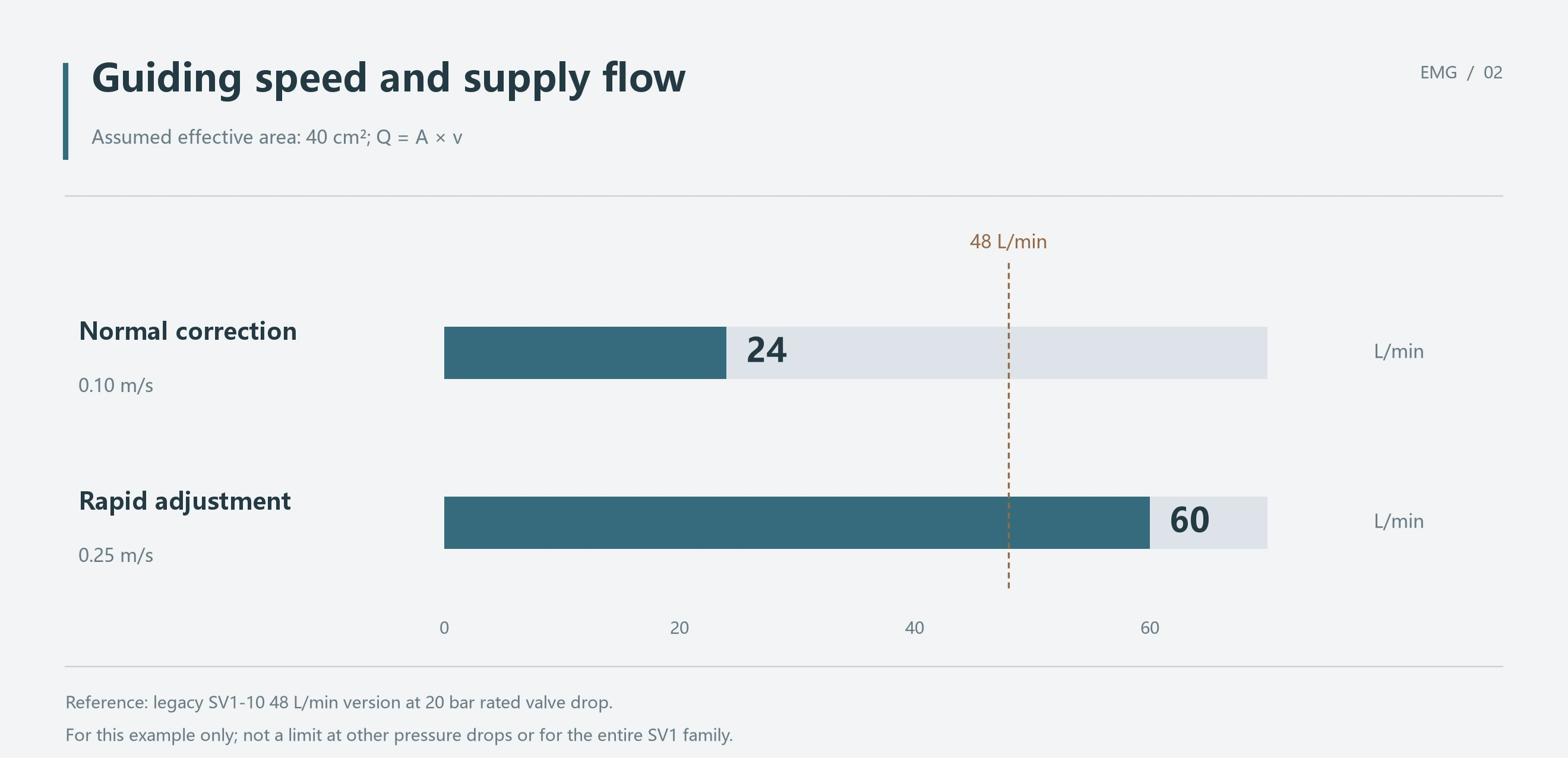
At the rated 20 bar drop, the 48 L/min version cannot cover a 60 L/min requirement. Evaluate a higher-flow size or a two-stage SV2 arrangement for this operating point. Retaining the 48 version would leave insufficient supply flow.
If more than 20 bar is available across the valve, reassess using its corresponding flow curve. There is no universal 60 L/min dividing line between single-stage and two-stage valves. Selection follows the required flow at the actual pressure drop.
A Strip-Guiding Machine Example
Assume a strip-processing line uses a hydraulic cylinder to move a guiding frame. The cylinder's effective area in the direction considered is 40 cm². Normal correction requires 0.1 m/s, while rapid adjustment requires 0.25 m/s. These are assumed conditions for selection analysis, not a customer test record.
Also assume that 20 bar remains available across the valve after allowing for load, return backpressure and line losses. Using the cited SV1-10 data sheet, the two speeds require 24 and 60 L/min respectively.
| Operating requirement | Supply demand | Assessment at the assumed 20 bar valve drop |
|---|---|---|
| Normal correction at 0.1 m/s | 24 L/min | The SV1-10 32 L/min version is a candidate, with 8 L/min nominal flow margin; dynamics and configuration still need checking |
| Rapid adjustment at 0.25 m/s | 60 L/min | The cited SV1-10 range's 48 L/min version is insufficient; a higher-flow arrangement is required |
| One valve performs both tasks | Peak requirement of 60 L/min | Size supply capacity for rapid adjustment and verify low-speed correction performance |
If the full 48 L/min enters the cylinder in this direction, Q/A gives only 0.20 m/s, below the 0.25 m/s target. This calculation assumes all flow reaches the cylinder and ignores actuator leakage. Even at full opening under the stated conditions, the 48 version cannot deliver the target speed.
If rapid adjustment remains a requirement, evaluate a larger size or an SV2 two-stage arrangement. The main stage must cover the actual 60 L/min operating point, with suitable pilot supply and return, main-stage transducer and amplifier. Select the specific SV2 model from its complete data sheet and flow curves.
If the machine needs only normal 24 L/min correction, a two-stage upgrade is not justified by stage count alone. First assess the SV1-10 32 version against response, overlap and installation requirements. The case for SV2 follows working flow and the supporting conditions.
Check Pilot Supply and Return for Low-Pressure Operation
SV2 uses hydraulic pressure to actuate its main stage. Even when the main circuit can supply the cylinder, check that the pilot can develop enough differential pressure to move the main spool. Assess pilot supply arrangement, pressure and return backpressure together.
This is especially relevant when the valve must move during unloading or at low supply pressure. Verify the selected model's pilot requirements first. If the existing supply and return conditions are inadequate, change the supporting arrangement; increasing main-stage size alone will not resolve the actuation problem.
The public product overview does not list minimum pilot pressures for every SV2 model. Obtain that value from the specific valve data sheet and original hydraulic diagram. General statements about low-pressure single-stage operation do not replace two-stage pilot requirements.
Match the Controller When Replacing SV2
The EMG iCON SV extension module provides an amplifier inner loop for two-stage servo valves and an analogue input for main-stage position feedback. Main-spool displacement is part of the control chain, so wiring and settings must match the valve.
For an older SV2 replacement, compare the complete valve, transducer and controller model designations together. Establish drive and feedback compatibility before adjustment under the corresponding documentation. Matching coil current alone does not establish correct main-stage tracking.
Follow the same chain when investigating machine behaviour. If the pilot produces output but the main stage does not track, start with actuation conditions and feedback. If main-stage tracking is normal but cylinder motion remains inadequate, check working flow, load and the actuator circuit. Measurements establish the actual fault.
Summary
If a specific SV1 version meets working flow at the actual pressure drop, continue evaluating the single-stage arrangement. In this article's 60 L/min requirement at 20 bar drop, the cited SV1-10 48 version is insufficient. A larger size or two-stage arrangement is needed.
With SV2, flow is only one part of selection. Pilot supply and return, main-stage position feedback, amplifier and mounting must all match. In SV2-16, SV1-10 acts as the pilot, so complete-valve performance must be verified together with the main-stage loop.