EMG Strip Guiding Oscillation: Checking Sensors, Valves and Cylinders
The strip drifts left, the mechanism corrects right, then reverses again without settling. Measurement fluctuations, cylinder sticking and guiding delay require different remedies.
For example, if the actual strip position is unchanged but its measured value jumps, the controller may repeatedly correct a false signal. A cylinder that pauses and then jumps points toward hydraulic or mechanical motion. Oscillation at low speed but normal operation at high speed also calls attention to transport delay from the sensor location.
The strip is stationary but the measured value jumps
An EMG guiding system combines detection, electronic control and an actuator. Sensors measure edge or center position; the controller outputs a command from the position error; the valve and cylinder move the mechanism, which changes strip position.
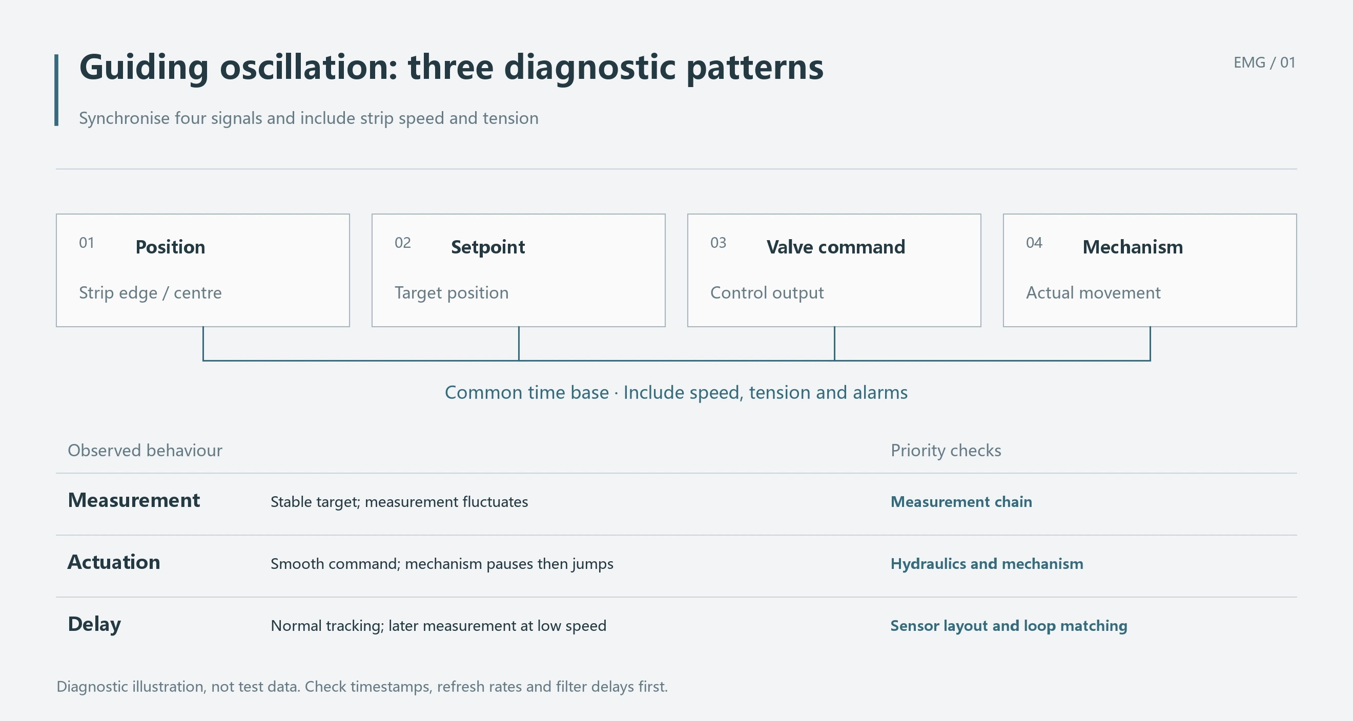
Record raw position measurement, guiding setpoint, valve command and actual mechanism position, along with strip speed. Use a common time base. Large differences in channel refresh rates or filtering can make display delay look like machine response delay.
During an approved stopped-machine inspection, establish that the target edge is stable and then inspect the raw measurement. If it still jumps, check loose sensor mounting, whether the target lies within the valid sensing range, and power and signal wiring.
If the raw measurement is stable but the displayed processed value jumps, check the processing channel, scaling and filtering. Both situations can present a fluctuating position to the controller, but the affected part of the signal chain differs.
Five symptoms and where to investigate
| Observed symptom | Check |
|---|---|
| Target position is stable but raw measurement jumps | Sensor mounting, sensing range, power and wiring |
| Command is steady but the mechanism pauses and jumps | Starting pressure, cylinder friction and guide binding |
| Cylinder moves during reversal but the roller frame does not | Linkages, pins and mechanical clearance |
| Cylinder follows normally but detection lags at low speed | Sensor distance, speed signal and low-speed control settings |
| Oscillation occurs only at a splice or tension transition | Tension and mechanical guiding changes in that process step |
For example, if oscillation appears only as a splice passes and the remaining strip runs steadily, compare splice passage and tension changes with the oscillation record. Repeatedly replacing the valve does not address that recurring disturbance.
Normal at high speed, oscillating at low speed
EMG uncoiler application material explains that limited space can require sensors after a deflector roll. Delay then exists between lateral uncoiler movement and its detected effect, potentially destabilizing the loop particularly at low strip speed.
The controller still receives the error from before the correction and continues output. By the time the sensor registers the change, the mechanism may have moved too far and the controller reverses. Accumulated correction can produce repeated oscillation.
Where a position change mainly travels downstream with the strip, distance divided by strip speed estimates that part of the delay. Roll constraints, tension and mechanism geometry also affect response, so L/v is a simplified transport time.
A 1.5 m sensing distance: how much does slowing down add?
Assume a processing line uses a hydraulic cylinder to move the uncoiler laterally, with a sensor after the downstream deflector roll. Take an effective transport distance of 1.5 m from a strip position change to the sensor and compare two speeds using the simplified transport model.
| Assumed strip speed | Estimated transport delay, L/v |
|---|---|
| 1.5 m/s | 1 s |
| 0.3 m/s | 5 s |
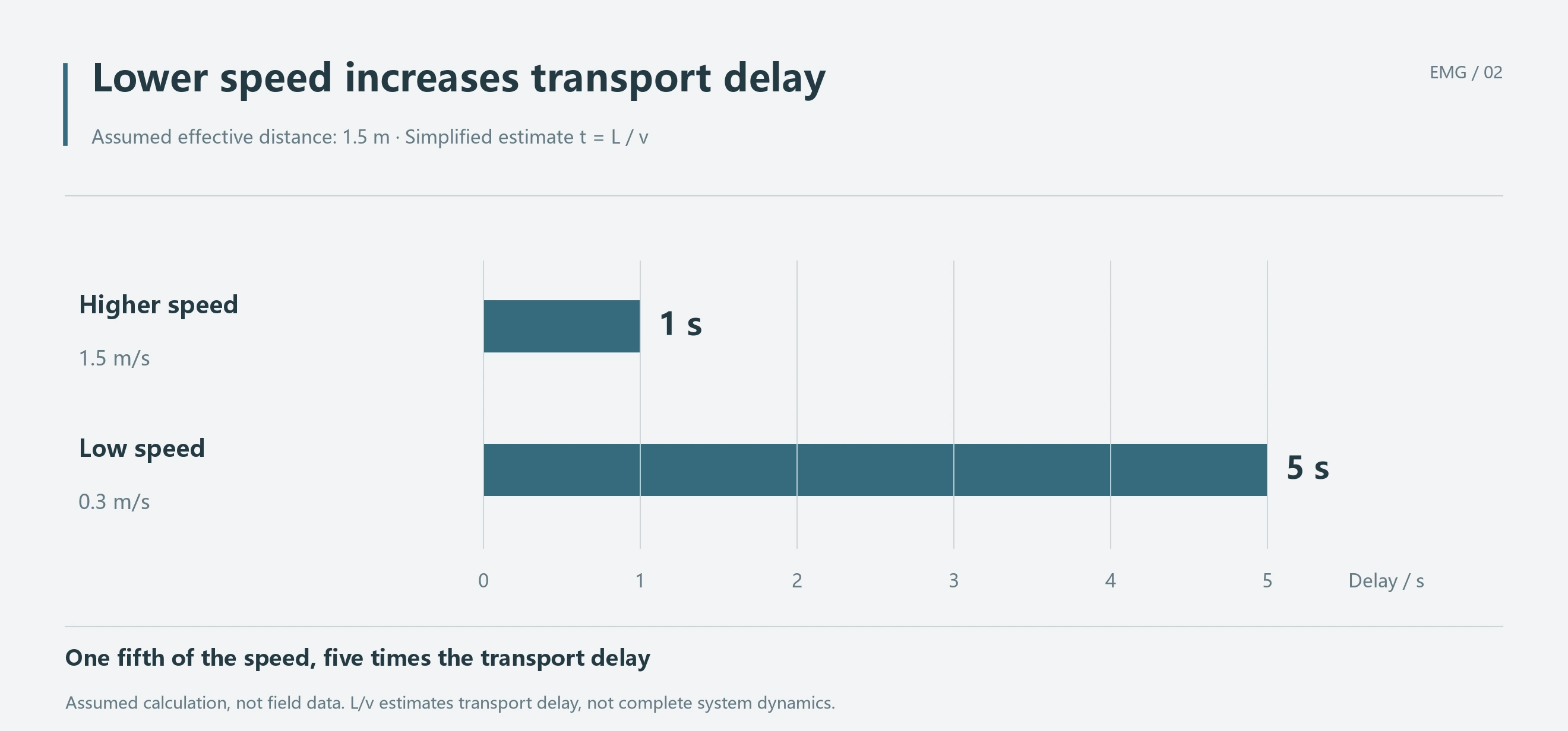
This is a calculation example. With distance unchanged, reducing speed from 1.5 to 0.3 m/s increases transport delay from one to five seconds. Continued correction while waiting for detection makes excessive movement more likely at low speed.
Assume the cylinder follows the valve command promptly and smoothly, but the detected strip response arrives noticeably later at low speed. Control output continues until after the measurement crosses zero, then reverses. Slow cylinder motion cannot explain that sequence; sensor location and low-speed settings deserve attention.
Check whether controller speed input agrees with actual speed, whether low-speed operation still uses the high-speed correction rate, and how far the mechanism travels before the detection arrives. If space prevents moving the sensor closer, low-speed correction must accommodate the longer delay.
After adjustment, retain the same low speed, tension and strip conditions and compare peak deviation, reversal count and settling time. Smaller oscillation with a persistent offset to one side still fails to achieve the guiding objective.
Steady command, followed by a pause and sudden movement
No movement at a small command followed by a sudden jump at a larger command can arise from guide or cylinder static friction, or insufficient hydraulic driving force. Record pressure and displacement around startup. Pressure building while the mechanism remains still, followed by sudden sliding, differs from measurement delay alone.
Mechanical clearance often appears during reversal. The cylinder or linkage moves while the roller frame remains stationary; only after clearance is taken up does the frame follow. Recording only cylinder position can miss this lost motion.
For SV2 systems with main-spool position feedback, compare command with spool position. If command changes but the spool does not move, investigate pilot drive and internal valve control. If the spool follows normally but the cylinder does not, continue with flow, pressure, the cylinder and mechanical mechanism.
With an effective cylinder area of 40 cm² and a target correction speed of 0.1 m/s, theoretical flow demand is 24 L/min. If actual flow is only 12 L/min, speed is approximately 0.05 m/s before leakage, half the target. This explains inadequate correction speed; whether oscillation results also depends on controller output during the lag.
Does reduced gain mean the fault is fixed?
Lower gain reduces mechanism action and may reduce oscillation. If the sensor still jumps or the mechanism still sticks, those problems remain. The parameter change has merely reduced the visible symptom.
Control tuning belongs to personnel familiar with the equipment, with original settings retained. Change one setting at a time and compare at the same speed and tension. Check recovery to the setpoint after a disturbance, rather than judging only the size of steady-state oscillation.
Locate the problem from the symptom
Stable strip position with a jumping measurement points to detection and signal channels. A steady command with pause-and-jump motion calls for hydraulic-drive and mechanical-friction checks. Cylinder movement without frame movement during reversal calls for a linkage-clearance check.
If the cylinder follows normally and detection lags noticeably only at low speed, examine sensing distance, actual speed and low-speed settings. In the 1.5 m calculation example, reducing speed to one fifth increases transport delay fivefold, changing the timing of the guiding loop.