EMG SV1-10/48/315/6 Servo Valve: Model Code and Selection
When replacing an EMG SV1-10 servo valve, the series name alone is not enough. The flow, pressure and overlap codes define its basic configuration. Drive current and terminal connections also need to match the installation.
EMG SV1 series and published models
The SV1-10/48/315/6 is an NG10 single-stage servo valve with a nominal flow of 48 L/min, a 30–315 bar operating pressure range and 6% nominal positive overlap.
EMG describes the SV1-10 as a single-stage, four-way, three-position proportional valve with an electromagnetic rotary drive and return springs. This describes its hydraulic function; servo valve is the manufacturer's product designation.
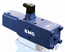
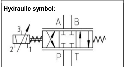
SV1-10/48/315/6 model code
| Code | Meaning | Selection detail |
|---|---|---|
| SV | Servo valve | Product series |
| 1 | Single-stage construction | Distinguishes the SV1 from the SV2 series |
| 10 | Nominal size NG10 | ISO 4401 NG10 / CETOP 5 hydraulic interface |
| 48 | Nominal flow of 48 L/min | Specified at ΔpN = 20 bar |
| 315 | High-pressure version | Operating range of 30–315 bar for the version covered here |
| 6 | Nominal 6% positive overlap | Listed overlap range of 4–8% |
The code does not fully specify the amplifier configuration, coil connections or every special option. The type code also includes C and D suffixes for HFC and HFD fluids. For replacement work, check the full nameplate and order record against the documentation for that valve.
The SV1-10 uses a rotary slide with gap adjustment. Its design provides low friction and high repeatability, together with manual operation and an in-service cleaning flush. Actual control accuracy depends on the complete system and operating conditions.
The manual mechanism supports functional checks and setup. The cleaning flush is a service feature; system filtration remains necessary. Follow the operating instructions for the specific valve when using either function.
SV1-10/48 flow and pressure drop
The /48 code identifies a nominal flow of 48 L/min at ΔpN = 20 bar. At ΔpN = 70 bar, the listed flow for the same size is approximately 70 L/min.
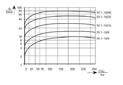
Supply pressure pS and valve pressure drop ΔpV are separate quantities. The 315 code identifies the pressure version, not the pressure drop used to rate the /48 valve. Pump outlet pressure alone does not establish the pressure drop available across the valve.
| Flow code | ΔpN = 20 bar | ΔpN = 70 bar |
|---|---|---|
| /4 | 4 L/min | 7 L/min |
| /8 | 8 L/min | 13 L/min |
| /16 | 16 L/min | 24 L/min |
| /32 | 32 L/min | 46 L/min |
| /48 | 48 L/min | 70 L/min |
For selection, I would calculate the actuator's flow requirement first, then check the valve pressure drop available under load. Matching the flow code alone can overlook changes in actuator speed at the actual operating pressure.
/1 and /6 overlap near neutral
Overlap here means positive overlap. The nominal /1 and /6 versions have listed overlap ranges of 0.5–2.5% and 4–8%, respectively.
The curves show different flow and pressure responses around neutral. The /6 version has a wider overlap region, while the /1 version begins changing flow at a smaller input away from neutral.
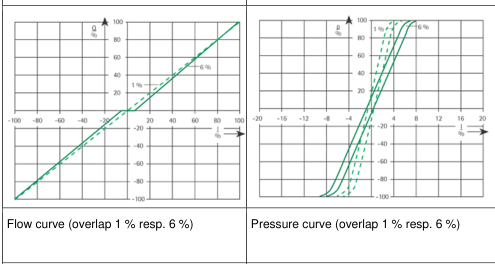
Smaller overlap does not automatically improve overall control. The controller, actuator, load and fluid condition all matter. When changing overlap in an existing system, recheck the response around neutral and the controller settings.
Typical internal leakage is specified at pS = 100 bar, I = 0 mA and an oil temperature of 50°C, with QA and QB both at 0 L/min. Under these conditions, the /48/315/6 version is listed at 1 L/min and the /48/315/1 version at 1.5 L/min.
External leakage is separately listed as zero. This does not mean zero internal leakage. The typical internal leakage figures above also do not describe operation at 315 bar.
Drive current and dither for the /48
Electrical ratings require a separate check during replacement. With terminals 1–2 connected, the /4, /8, /16 and /32 versions are rated at ±300 mA. The /48 version is rated at ±1000 mA.
For the /48 using terminals 1–2, the listed resistance is 11 Ω and inductance is 0.05 H. The dither values are 40 mA at 50 Hz and 80 mA at 150 Hz. Check the electrical ratings for the actual flow size.
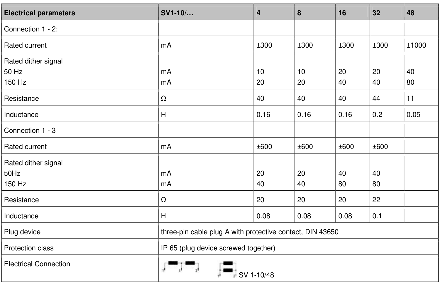
Dither is an oscillating signal superimposed on the control current. Its settings must match the driver. The amplitude convention is not identified as peak, peak-to-peak or RMS in the parameter table, so these values should not be converted directly into an amplifier percentage setting.
An alternative connection using terminals 1–3 is also listed, but the /48 column is blank for that connection. The ±600 mA rating shown for other flow sizes must not be applied to the /48 by assumption.
I would check rated current, terminal numbering and dither settings together. Even with matching hydraulic ratings, these details affect whether the existing amplifier is suitable. Confirm the connections against the documentation for the installed valve.
Frequency response at 20 bar and 200 bar
The frequency-response plots cover supply pressures of pS = 20 bar and pS = 200 bar. Each distinguishes input amplitudes of I/IN = 10%, 30% and 100%. Read the magnitude and phase responses together.
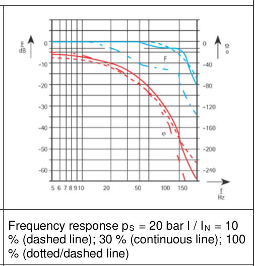
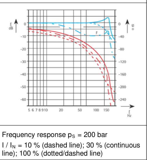
Supply pressure and input amplitude are part of the conditions for interpreting dynamic performance. The supply pressures in these plots are also distinct from the nominal valve pressure drops used in the flow table.
The plots do not explicitly assign an individual curve to the complete SV1-10/48/315/6 model, nor do they establish a single guaranteed bandwidth for that configuration. Confirm model-specific dynamic performance under the relevant test conditions.
Where a project has a defined response requirement, obtain the test conditions or manufacturer confirmation for the complete order code. System bandwidth also depends on the actuator, load, hydraulic circuit and controller. A valve frequency-response plot does not establish the machine's closed-loop bandwidth.
Selecting for a strip-guiding system
EMG includes its SV servo valves in the actuator and hydraulic range for strip-guiding systems. In metal strip position control, the valve works with sensors, control electronics and the actuator to correct strip position.
Start with the actuator's required flow, available valve pressure drop and operating pressure range. Then check overlap, drive current and connections. Fluid and filtration requirements should be checked against the same documentation version.
The version covered here recommends VG46 mineral oil and lists a cleanliness requirement of 17/15/12 to ISO 4406:1999. It also lists SAE AS 4059 class 7 and NAS 1638 class 6. Check filtration requirements separately when working with a different version.
For an existing installation, keep a full nameplate photo, the original equipment documentation and the amplifier settings. Compare these with the parameters for the matching valve version. Confirm special fluids, suffixes or connection arrangements against the actual unit before replacement.