EMG SV1-10 1% vs 6% Overlap: Null Response, Leakage and Selection
The /1 and /6 versions of the EMG SV1-10 both have positive overlap. The smaller overlap of /1 brings the flow-opening transition closer to null. The larger overlap of /6 comes with lower typical null leakage under the conditions listed in the manufacturer data sheet. Selection depends on fine-correction requirements and acceptable null leakage.
For an existing valve replacement, retain the original overlap configuration first. Changing from /6 to /1 requires assessing both null response and leakage. Changing from /1 to /6 requires checking that the existing control settings still meet small-signal correction requirements. Matching flow and pressure codes alone does not establish equivalence.
All parameters below come from manufacturer data sheet DB_SV1-10_05_en, document ID EMGDES-00002822. They describe that documented version and are not universal specifications for every generation of SV1 valves.
What /1 and /6 Specify
| Suffix | Nominal overlap | Range listed in the data sheet |
|---|---|---|
| /1 | 1% | 0.5%–2.5% |
| /6 | 6% | 4%–8% |
Positive overlap means the metering edges retain a degree of coverage at the neutral position. The valve must pass through this transition before an effective working-port opening develops. Although /1 has a small nominal value, it still has positive overlap and should not be selected as a zero-lap valve.
The 1% and 6% figures are not flow-loss percentages, leakage rates or control accuracies. They identify overlap configurations whose effects need to be assessed using the flow–signal and pressure–signal curves.
Focus on the Flow Curve near Null
The data sheet plots the 1% and 6% configurations together. Their large-signal flow trends are similar; the more relevant difference lies near zero, where overlap changes the transition from a small command to an effective flow opening.
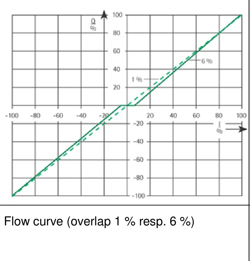
For frequent, small corrections in both directions, prioritise /1 for evaluation. Smaller overlap reduces the transition associated with geometric coverage, while actual breakaway still depends on drive conditions, friction, hydraulic load and control settings.
If an existing /6 valve produces little motion at small commands, compare actual input current, valve pressure drop and mechanism movement before attributing the behaviour to overlap. A stationary mechanism can also reflect cylinder friction or supply conditions.
The original pressure curves likewise show different pressure build-up characteristics near null. Pressure build-up does not establish cylinder movement on its own; load, friction and pressures on both sides of the actuator also determine breakaway.
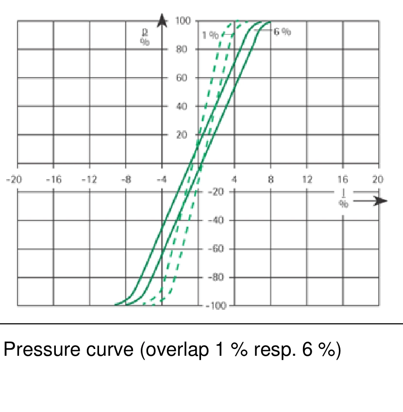
Lower Typical Null Leakage for /6
The table below compares only the 315 pressure version. Test conditions are 100 bar supply pressure, 0 mA input current, 50 °C temperature, and QA=QB=0. These are typical internal leakage figures, not field acceptance limits.
| Rated flow version | /315/6 typical internal leakage | /315/1 typical internal leakage |
|---|---|---|
| 4 L/min | 0.15 L/min | 0.25 L/min |
| 8 L/min | 0.25 L/min | 0.4 L/min |
| 16 L/min | 0.4 L/min | 0.7 L/min |
| 32 L/min | 0.7 L/min | 1 L/min |
| 48 L/min | 1 L/min | 1.5 L/min |
For every flow version in this comparison, /6 has the lower typical value under the same test conditions. For the 48 L/min version, the difference is 0.5 L/min. Using 100 bar for an energy estimate, that difference corresponds to approximately 0.083 kW of hydraulic power, illustrating the scale involved.
Internal leakage cannot be converted directly into cylinder creep speed. The listed test conditions specify zero working-port flow. Actuator movement also depends on working-port pressure distribution, cylinder leakage and the load-holding circuit. Reliable load holding must be addressed in the complete hydraulic design.
Choosing for a Guiding Application
Assume a hydraulic cylinder moves a strip-guiding frame with an effective area of 20 cm² in the direction considered. A faster correction speed of 0.02 m/s requires 2.4 L/min. Fine correction at 0.001 m/s requires 0.12 L/min. These are calculation examples, not field measurements.
With a 16 L/min rated version, 2.4 L/min is 15% of rated flow and 0.12 L/min is only 0.75%, assuming rated pressure drop and an ideal linear opening region. These proportions indicate the scale of the demand; they do not predict the command needed to cross the overlap region.
| Assumed duty | Required flow | Overlap-selection priority |
|---|---|---|
| Faster correction at 0.02 m/s | 2.4 L/min | Check actual pressure drop and motion response for each configuration |
| Frequent fine correction at 0.001 m/s | 0.12 L/min | Evaluate /1 first for its small-signal transition, while allowing for higher typical null leakage |
| Mainly stationary at null, with less demanding fine correction | Calculate from the actual movement | If /6 meets breakaway and tracking requirements, its lower null leakage is a useful selection benefit |
For the fine-correction example, changing /6 to /1 is an option to evaluate. The 0.75% proportion alone does not establish that the cylinder will start moving. At comparable temperature, load and pressure drop, record current, mechanism position and working-port pressures to compare breakaway, reversal and settled error.
If the duty mainly involves remaining at null and /6 already meets motion requirements, smaller overlap alone is not a reason to replace it. Meeting the process requirement while reducing null leakage is also a valid choice.
Revalidate Control Settings after Changing Overlap
Positive overlap affects small-signal response. Any deadband compensation, breakaway compensation or integral settings in the original controller may therefore need review. Verify retained settings rather than assuming compatibility from a similar model code.
In particular, after a change from /6 to /1, compensation previously used to cross a larger null transition may produce excessive initial movement. This is a test priority, not a guaranteed outcome; it depends on the control strategy and load.
Check the complete model, drive connection, rated current, pressure version and overlap when replacing a valve. In the cited data sheet, rated currents differ across some flow versions and connections. Selecting overlap does not replace electrical compatibility checks.
Summary
Evaluate /1 first for frequent small-signal correction, accepting its higher typical null leakage in the cited data sheet. If motion requirements are met, /6 offers lower typical null leakage. Both configurations have positive overlap.
Retain the original configuration for replacement unless there is a reason to change it. If overlap changes, compare breakaway, reversal, tracking and neutral behaviour under matched conditions. Overlap alone guarantees neither positioning accuracy nor load-holding performance of the complete circuit.