EMG SV1 Slows When Warm: Four Symptoms and What They Mean
Warm-operation slowing can take several forms: supply pressure falls during movement, actual current drops despite an unchanged command, cylinder speed falls with comparable supply and current, or the cylinder moves normally while the strip-position indication responds later. Each directs the investigation to a different part of the system.
The following four scenarios are hypothetical. Their figures illustrate diagnosis, not SV1 acceptance limits. Compare similar loads, positions and travel, accounting separately for starting, stopping and end-position effects.
Example 1: Pressure falls during movement and the cylinder slows
An uncoiler guide moves 20 mm in 2 seconds at 35 °C and 4 seconds at 55 °C. Actual current remains approximately 120 mA, but dynamic supply pressure at the SV1 inlet falls from 90 to 55 bar.
Assume this machine's circuit calculation requires at least 70 bar at that point to meet the load and required pressure losses. Warm pressure is below that requirement, so the supply circuit comes first. The 70 bar figure belongs to this example, not a universal SV1 minimum operating pressure.
The observable combination is acceptable-looking stationary pressure followed by falling pressure and speed when guiding starts. If other movements sharing the same source also deteriorate, investigate the common supply rather than only this SV1.
Maintenance should compare pump-outlet and valve-inlet pressure during movement, then check regulation, unloading and intervening losses. If pump pressure holds while valve-inlet pressure falls, prioritise the path between those points. If both fall, investigate common supply capacity, regulation and unloading.
For example, finding an unloading circuit that opens incorrectly when warm, repairing it and restoring both inlet pressure and the approximately 2-second movement verifies a correction. Pressure loss alone does not establish pump wear.
Example 2: Pressure is similar, but actual current falls
On another installation, dynamic inlet pressure remains approximately 90 bar during the same comparison movement, and the requested controller output is unchanged. Actual coil current falls from 120 mA cold to 60 mA warm, while the 20 mm movement increases from 2 to approximately 4 seconds.
The first established change is drive output. The valve receives different current, so these two movements cannot directly establish changed hydraulic valve performance. Check drive thermal protection, supply voltage, connections, wiring and output capability.
A driver entering a thermal current limit can produce this combination: command present, lower current and slower motion. If the specified correction restores current and movement time, that supports an output-limitation diagnosis.
Current and speed need not fall in the same proportion. Speed also depends on opening, load and pressure differential. The times here are example observations, not values calculated from the current ratio.
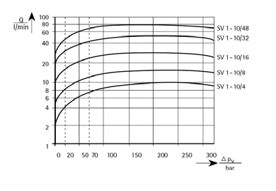
After a driver replacement, check the actual version. DB_SV1-10_05_en lists ±300 mA for grades 4 through 32 on connection 1–2, and ±1000 mA for grade 48. Driver capacity must match the installed configuration.
Example 3: Comparable supply and current, increased cylinder bypass
In a third case, inlet pressure, actual current and available supply flow remain comparable, but the cylinder slows at the same load. Some installations may also show increased position drift. Use the specified tests to separate valve, cylinder and load-side effects.
A simplified calculation shows how piston-seal bypass changes speed. Assume a cap-end effective area of 20 cm² and inlet flow of 1.2 L/min in both conditions. Applicable testing establishes that piston-seal bypass increases from 0.2 to 0.6 L/min at comparable pressure conditions.
After bypass is deducted, effective displacement flow falls from 1.0 to 0.6 L/min. Ignoring compressibility and other effects, speed falls from approximately 8.3 to 5 mm/s. A 20 mm movement consequently increases from approximately 2.4 to 4 seconds.
Inlet flow has not fallen, but less of it produces movement. With increased bypass confirmed by cylinder testing, the cylinder seals and mating surfaces belong in the repair investigation rather than replacing only the SV1.
Increased valve internal losses can also reduce flow reaching the actuator. Comparable pressure and current with slower movement therefore advances the investigation to internal losses; component-specific results distinguish valve from cylinder. Movement return includes normal displaced oil and is not directly equivalent to valve leakage.
Example 4: Cylinder speed is unchanged, but position response is delayed
Suppose the same 20 mm movement takes 2 seconds both cold and warm, yet guiding appears slower later in production. If line speed also changes, check sensing delay first.
Assume corrected strip travels approximately 2 m from the mechanism to a downstream measuring point. Transport time is about 2 seconds at 1 m/s and 4 seconds at 0.5 m/s. The cylinder can move at its original speed while the sensor sees the result later.
This pattern points toward line speed and sensing geometry. Compare actuator movement, strip speed and sensor indication on the same timeline. Total response also includes mechanism, strip and control dynamics, so strip recentring time is not a substitute for cylinder movement speed.
Match the observation to the next check
| Observation | First investigation | Further confirmation |
|---|---|---|
| Inlet pressure falls during movement; current remains similar | Supply path, regulation and unloading | Restored supply restores movement at the same load |
| Same command; actual current falls when warm | Driver, power and wiring | Current and movement time recover together |
| Comparable supply and current; slower cylinder or increased drift | Valve/cylinder internal losses and load side | Specified separate tests locate the loss |
| Similar cylinder time; later position indication or recentring | Strip speed, sensing distance and control dynamics | Delay changes correspond to transport and sensing behaviour |
Without specialist measurements, operators can record temperature, travel, time, existing pressure indications and alarms. Actual-current verification, pressurised measurements and isolation tests belong to maintenance. Do not improvise by disconnecting returns or blocking ports.
Identify which quantity changed. Falling pressure directs attention to supply; falling actual current to the drive. Comparable supply and current with slower motion calls for internal-loss investigation. Normal cylinder movement with later indication calls for line-speed and sensing checks. Verify corrections under equivalent operating conditions.