EMG Uncoiler vs Recoiler Guiding: Sensors, Actuators and Control Objectives
Uncoiler guiding controls where strip enters the line. Recoiler guiding controls how strip aligns with the mandrel as it is wound. Both can use hydraulic cylinders to move the mandrel laterally, but the uncoiler adjusts the outgoing strip position while the recoiler follows the incoming strip.
If the strip is already off position at the entry, check uncoiler measurement and entry guiding first. If the entry is correct but position changes before recoiling, investigate the downstream process and verify recoiler tracking. Separating these observations helps identify where the deviation begins.
The comparison below covers typical EMG arrangements with laterally movable uncoilers and recoilers. Lines using other guiding mechanisms require analysis of their own geometry.
Similar Lateral Motion, Different Position Relationships
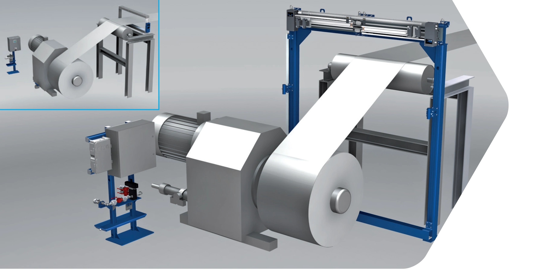
At the entry, lateral movement of the mandrel and coil changes the position of strip entering the line. Sensors detect edge or centre deviation, and the controller drives the servo valve and hydraulic cylinder to return the outgoing strip to the selected reference.
After passing through upstream rolls and processing sections, strip can reach the recoiler at a different lateral position. The recoiler follows that movement so each new wrap aligns with the selected edge or centre reference. It tracks incoming strip to build an aligned coil.
| Comparison | Uncoiler guiding | Recoiler guiding |
|---|---|---|
| Main objective | Position strip entering the line | Control strip position relative to the mandrel for aligned winding |
| Typical moving assembly | Uncoiler mandrel and coil | Movable part of the recoiler |
| Main observation | Whether outgoing strip reaches the selected reference | Whether the recoiler follows incoming strip and maintains coil alignment |
| Sensing priority | Detect the effect of uncoiler adjustment promptly | Maintain the measurement reference relative to recoiler movement |
| Common misinterpretation | Treating a distant measurement as an immediate response | Considering strip position relative to the fixed frame while overlooking mandrel movement |
Check control direction against measurement polarity, cylinder movement and mechanism layout using the documentation for the installed system.
Why Sensor Layouts Cannot Simply Be Copied
Uncoiler sensing needs to detect the effect of lateral adjustment promptly. EMG application literature explains that limited space can place the sensor downstream of a deflector roll, introducing a delay between actuation and measured response. This can particularly affect stability at low strip speed.
During an uncoiler retrofit, determine sensor location together with the control arrangement. If the measurement distance changes, revalidate the delay between motion and measured response, including low-speed operation.
At the recoiler, sensing must represent deviation relative to the movable recoiling assembly. EMG's typical arrangement places the sensing system close to the deflector roll and associates it with the movable part of the recoiler. This can use a mechanical connection or electronic synchronisation.
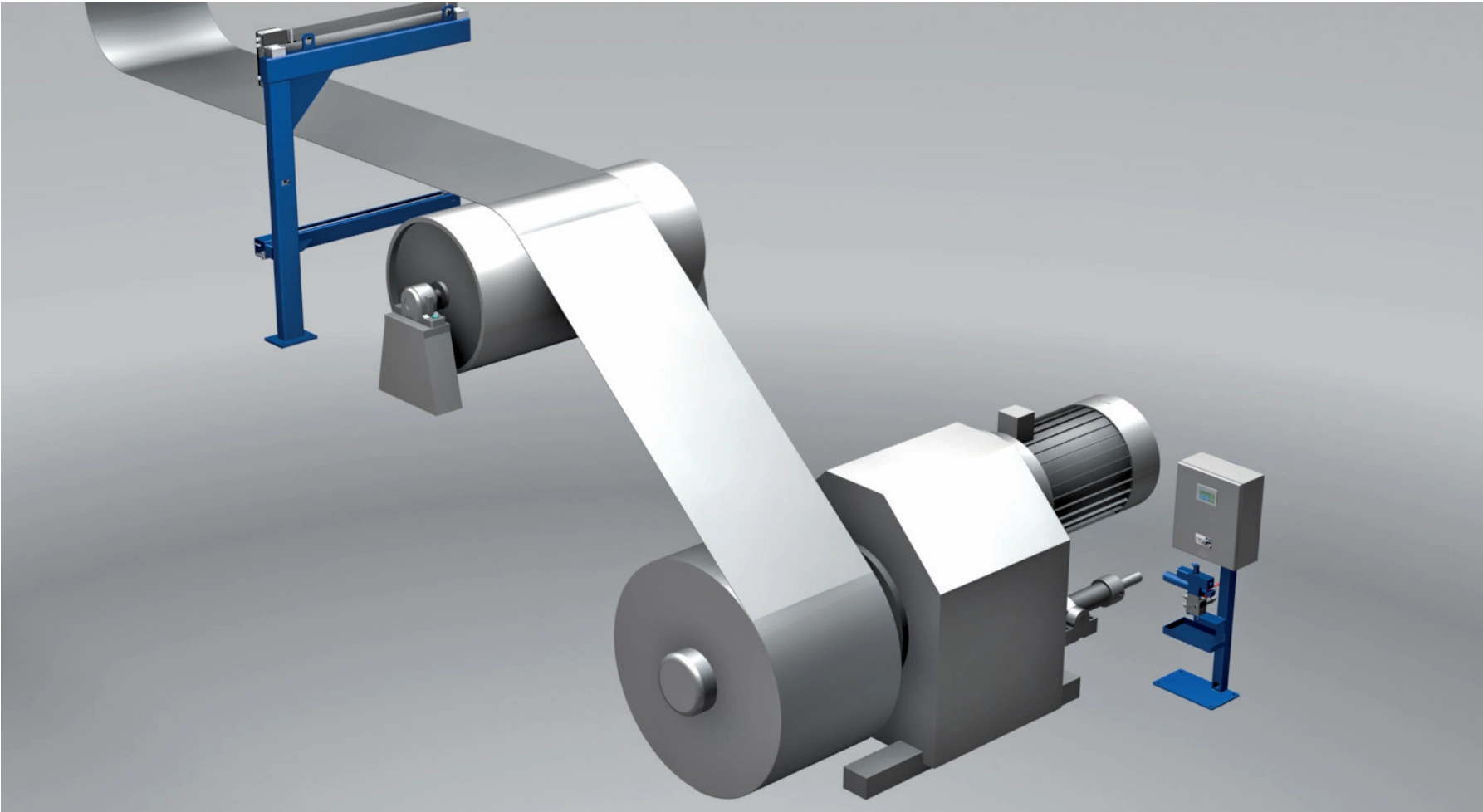
When the recoiler moves right, the measurement reference must correctly account for that movement. In lateral coordinates, the relevant error is strip-edge position xstrip minus recoiling reference position xcoil. Mechanical association or electronic synchronisation enables the controller to use the correct relative deviation.
Comparing Both Ends of a Processing Line
Assume a strip line consists of an uncoiler, processing rolls and a recoiler. Entry guiding uses strip centre position; recoiling aligns a selected strip edge. The following assumed conditions illustrate investigation priorities.
| Assumed observation | Priority checks | Reason |
|---|---|---|
| Immediately after uncoiling, strip centre is 5 mm right of the entry reference | Uncoiler sensing and lateral control | Strip is already off target at entry |
| Uncoiler exit is centred, but strip slowly shifts 3 mm right before recoiling after the processing section | Upstream process and rolls, plus recoiler tracking | The change occurs downstream and should not simply be assigned to uncoiler compensation |
| Recoiler has moved 3 mm right, but measurement continues to report the same uncorrected deviation | Recoiler measurement reference, synchronisation and control direction | Confirm that sensing correctly represents the relative position after movement |
For the third observation, first establish that incoming strip has not continued to move and that the recoiler actually completed its lateral movement. If both are confirmed but the reported error remains unchanged, prioritise the measurement reference and synchronisation. Increasing valve output may move the mechanism further without resolving the measurement issue.
In this assumed line, uncoiler control establishes entry alignment while recoiler control establishes winding alignment. Intermediate processes such as trimming may still need their own guiding equipment to meet local position requirements.
Edge Alignment and Centre Alignment Produce Different Results
If the process requires one edge to remain at a fixed reference, organise control around that edge. If it requires the strip centre to stay aligned with the line, use sensing and control that represent centre position. Width changes produce different outcomes under these two objectives.
For example, consider width increasing from 1000 to 1020 mm. Holding the centre fixed moves each edge outward by 10 mm. Holding one edge fixed moves the centre by 10 mm. With the wrong reference, the controller can reduce its error to zero while the resulting strip position still fails the process requirement.
Recoiling commonly requires aligned edges. EMG also identifies centre guiding for natural-edge strip and products that need to feed centrally into subsequent processing. Establish the product requirement before choosing the measurement and control reference.
Coil Misalignment Also Requires Tension and Deflector-Roll Checks
Recoiler control depends on stable strip transport. EMG emphasises adequate contact with the deflector roll, including wrap angle and stable tension. If strip slips or tilts on the roll, lateral recoiler movement alone cannot ensure satisfactory winding.
Compare measured error, actual recoiler movement and coil build together. If lateral tracking is normal but winding remains uneven, prioritise tension, roll contact and process conditions. If commanded movement is not achieved, investigate hydraulic actuation, mechanical resistance and available travel.
Summary
The uncoiler positions outgoing strip at the entry reference; the recoiler follows incoming strip to maintain winding alignment. These different objectives require separate decisions about sensing layout and control settings.
For deviation already present at entry, start with the uncoiler. For changes arising after processing, check that section and recoiler tracking. If the recoiler moves but reported deviation remains unchanged, investigate relative measurement and synchronisation. Persistent coil misalignment also calls for tension and deflector-roll contact checks.