Rexroth Proportional Relief vs Reducing Valves for Clamping
A shared power unit supplying higher-pressure processing and lower-pressure clamping generally needs separate main pressure limitation and branch reduction. A proportional relief valve controls its upstream pressure; a reducing valve regulates the downstream branch.
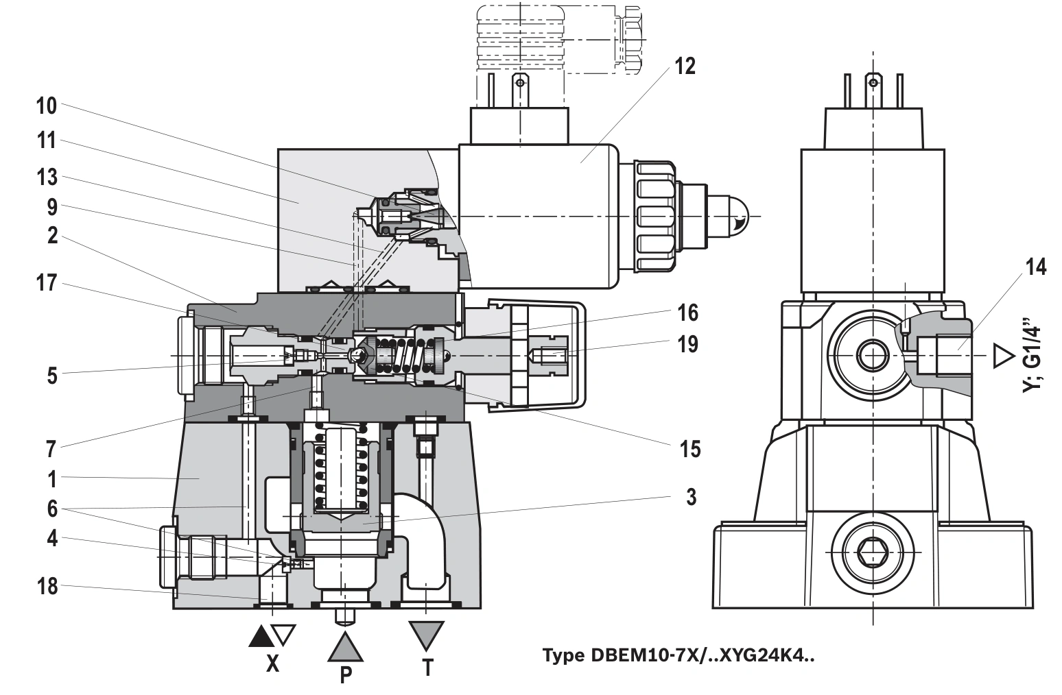
Examples use DBEM7X RE29361/2013-07 and 3DREP/3DREPE6 2X RE29184/06.11. The 3DREP is an OEM comparison example, not a claim of website inventory availability.
An 80 bar main circuit with a 30 bar clamp
Assume processing requires 80 bar. A 50 cm² clamping cylinder at 30 bar provides approximately 15 kN ideal force. Limiting the whole supply to 30 bar with the main relief prevents simultaneous 80 bar processing.
Maintaining an 80 bar main supply and using a suitable proportional reducing valve in the clamp branch can provide 30 bar downstream within the applicable regulating conditions. Clamping pressure need not be obtained by lowering the entire power-unit pressure.
A branch relief does not automatically replace a reducer
Connecting a 30 bar relief to a branch directly connected to an 80 bar main line can continuously discharge main flow to tank. Pump flow and connecting resistance determine the resulting pressures; stable simultaneous 80 and 30 bar operation is not established by that arrangement.
A reducer modulates the passage from main supply to branch to regulate downstream pressure. A relief discharges oil when its upstream pressure reaches the applicable condition. Their controlled sides and circuit positions differ.
A dedicated small pump supplying one clamping pressure may use relief regulation appropriately. Simultaneous different pressure levels on a shared supply call for assessing branch pressure reduction.
Check inlet pressure separately from adjustment range
RE29184/06.11 lists 3DREP/3DREPE6 2X at a maximum operating pressure of 100 bar and maximum flow of 15 L/min, with 16, 25 and 45 bar pressure ranges. A 30 bar target needs a range covering it; the 25 bar version cannot meet that target.
The 80 bar example is below that inlet limit. A real 180 bar main line would exceed it even if the clamp required only 30 bar. Select a solution suitable for the actual inlet pressure.
Main-stage DBEM relief flow and mounting capability require their own configuration data. A small pilot-control component such as DBET cannot directly replace a main-flow relief valve.
A three-way reducer also handles downstream pressure rise
The cited 3DREP uses three-way pressure reduction. When the controlled working-port pressure exceeds the setting, the spool can connect that port to T. De-energised behaviour depends on the actual spool configuration. Analyse this discharge path with holding requirements.
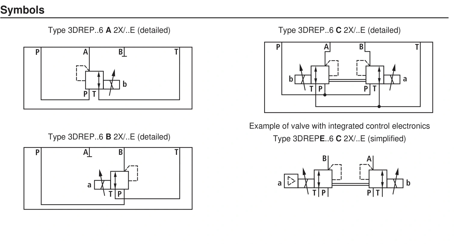
Workpiece deformation or an external mechanism pushing the cylinder can raise clamping-chamber pressure. Controlled pressure release and preventing clamp release are different process requirements. Define the full circuit's states after electrical loss, pressure loss and intentional unloading.
Proportional pressure regulation is not itself dependable load locking. A maintained 30 bar command does not establish clamping force after power loss. Spool symbols, holding devices and control logic must satisfy the machine requirement together.
Approach flow can determine valve size
A 50 cm² area moving at 100 mm/s requires 30 L/min, exceeding the cited 3DREP6 maximum of 15 L/min. Selecting only by a 30 bar target misses the approach-flow requirement.
At 20 mm/s, theoretical inlet flow is 6 L/min, allowing further assessment within that flow range. Characteristics, losses and regulation still need checking; a maximum flow listing does not guarantee every pressure/flow combination.
| Process requirement | Selection implication |
|---|---|
| One regulated pressure for the entire system | Assess main supply-pressure control |
| Simultaneous high-pressure processing and lower-pressure clamp | Assess proportional branch reduction |
| 30 L/min clamping approach | A 15 L/min component is insufficient |
| External force can raise chamber pressure | Define three-way discharge and return conditions |
| Workpiece must remain held after power loss | Design and validate holding separately |
Pressure reduction also dissipates energy
Reducing 80 to 30 bar at a continuous 6 L/min dissipates approximately 50 × 6 / 600 = 0.5 kW. Once motion stops and only small leakage is replenished, flow through the reducer is much lower. Motion flow must not be assumed continuously.
Substantial continuous return after clamping warrants checking required process flow, relief, leakage and open passages. Significant continuous throttling loss requires both a sustained differential and sustained flow.
Select by simultaneous pressure requirements, motion flow and stopped holding duty. Distinguish main limitation from branch reduction, and inlet pressure from regulated pressure range, to avoid substituting components with similar pressure numbers but different functions.