Proportional Pressure Valves: Pressure Drops during Motion
A machine reaches 100 bar while stationary but indicates only 80 bar when the cylinder moves. Start with the gauge location, required flow and pressure-valve function. The difference can reflect normal load pressure, insufficient delivery or circuit losses. It does not by itself establish a defective valve.
The moving load may require only 80 bar
Assume an effective cylinder area of 50 cm² and a movement load of 40 kN. Ignoring return pressure and friction, the required pressure is about 80 bar. With a 100 bar relief setting, the cylinder may move steadily near 80 bar because that is what the load requires.
At a mechanical stop, movement ends while the pump continues delivering. Pressure then rises to the 100 bar relief setting. Under these assumptions, 80 bar during travel and 100 bar at the stop is consistent with the force balance.
If the process requires 45 kN, however, 80 bar provides only 40 kN of ideal force. The output is insufficient and the missing pressure requires investigation. Judge the behaviour against the required output, rather than expecting the gauge always to match the relief setting.
A 20 L/min supply cannot sustain a 32 L/min requirement
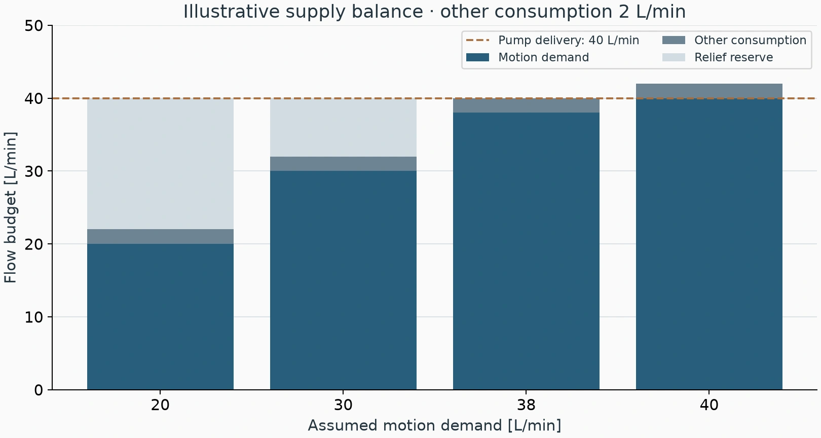
Assume the motion requires 30 L/min and leakage plus other branches consume another 2 L/min. If the pump can deliver only 20 L/min at that operating point, the sustained deficit is 12 L/min. Without another effective supply, the original speed and pressure cannot both be maintained.
An accumulator may temporarily cover the deficit, allowing an initially normal movement followed by falling pressure. Repeated cycles can make this more evident. Include usable accumulator volume and recharge time; pump nameplate maximum flow alone is insufficient.
Alternatively, a measured 40 L/min supply with 30 L/min motion demand and 2 L/min other consumption leaves 8 L/min available for relief regulation. If motion demand rises to 40 L/min, total demand becomes 42 L/min. The regulating reserve has disappeared and a 2 L/min deficit remains.
Find the missing 20 bar between pump and cylinder
A pump-outlet gauge does not include downstream pressure losses. Suppose the pump reads 100 bar, the directional-valve inlet 95 bar and the cylinder inlet 80 bar. One section loses 5 bar and the next loses 15 bar, identifying where further measurements should focus.
Passage losses generally increase with flow. A machine that works at low speed but loses force during rapid travel calls for pressure comparisons across valves, lines, filters and fittings at that higher flow. Include the return pressure in the cylinder force balance.
At 30 L/min, a 20 bar pressure loss dissipates approximately 20 × 30 / 600 = 1 kW. Pressure measurements can help locate losses when heating accompanies the symptom. A hot valve body alone does not identify where all the heat originated.
Establish whether the valve controls pilot or main flow
The Rexroth DBET6X is a small-flow proportional pressure-control component. RE29162/07.08 lists a maximum of 2 L/min, with additional pressure-range conditions. It can perform the appropriate pilot-control duty; it cannot directly handle a main relief flow of several tens of litres per minute.
The DBEM7X represents a different main-stage proportional relief arrangement. RE29361/2013-07 lists maxima of 275 L/min for the size-10 subplate version and 200 L/min for the G-threaded version, subject to the relevant configuration and operating characteristics. Its mechanical pressure-limiting function must also be interpreted for that configuration.
These separate catalogs distinguish control levels. One series' flow capacity must not be assigned to the other. If a small proportional valve remotely controls a main relief stage, inspect both the pilot circuit and main stage before concluding that replacing one component has corrected the fault.
| Observation | Check first | Interpretation |
|---|---|---|
| 100 bar stopped, 80 bar moving, required speed and force achieved | Load requirement and pressure ceiling | May be normal load pressure |
| Pressure falls further as speed increases | Actual pump delivery and series losses | Supply shortage or increasing restriction deserves priority |
| Pump pressure normal, cylinder pressure low | Valves and lines between those points | Locate the section carrying the loss |
| Command stable, actual coil current falls | Amplifier supply, drive and connections | Electrical output can alter pressure control |
| Initially normal, deteriorates over repeated cycles | Temperature, hot leakage and replenishment | Compare the same motion at defined temperatures |
A 100% command does not verify coil drive
A suitable amplifier drives the proportional pressure valve. Controller command, amplifier output and actual coil current are different stages. Supply sag, current limiting or a connection problem during movement can change the current and therefore the pressure-control response.
First record whether the controller command changes. Personnel qualified for the electrical work can then measure the drive according to its documentation. A stable voltage command does not exclude a drive-side change, and an unmeasured change does not justify declaring the coil defective.
With limited tools, collect three repeatable comparisons
Record stationary versus moving pressure and travel time; compare slow versus fast travel; then compare cold operation with normal operating temperature. Keep the load, stroke and measuring points consistent.
For example, a 200 mm stroke taking 4 seconds cold and 6 seconds hot, accompanied by a lower moving pressure when hot, directs further investigation toward hot delivery and leakage. If pressure alone falls while required speed and force remain satisfactory, recalculate the load requirement before dismantling the valve.
Calculate required load pressure and motion flow, locate pressure losses, then verify the control level and actual electrical drive. Those comparisons give the 100 bar setting a useful diagnostic context.