Rexroth HED 8: Switching and Reset Pressure
In a clamping circuit, a HED 8 changes its contact state when pressure reaches the switching threshold. The controller can then permit the next operation. As pressure falls to the reset threshold, the contact returns. Both thresholds matter; checking only the rising-pressure signal leaves part of the control function untested.
This article uses configurations such as HED8OH-2X/100K14A and the RJ50061 edition 2017-08 catalog. The HED 8 is a piston-operated pressure switch with electrical contacts, rather than a continuous pressure transmitter.
The /100 adjustment range and pressure rating are different
The cited edition offers maximum adjustment ranges of 50, 100, 200, 350 and 630 bar. The /100 version has a decreasing-pressure adjustment range of 10–100 bar. For that range, the NBR/FKM version has a separately listed pressure rating of 350 bar. Adjustment range and permissible pressure serve different purposes.
A 90 bar clamping confirmation point can therefore be considered within the /100 range. A target near 180 bar requires a suitable range such as /200; further turning of the /100 adjustment cannot establish that capability.
OH identifies a flange connection, K14 the corresponding DIN electrical connection, and A a graduated adjustment arrangement. The scale supports initial adjustment; accurate setting requires a pressure gauge. Mounting, sealing faces and connector type must also match the installation.
Switching at 90 bar does not mean resetting at 89 bar
The mechanical arrangement has a switching differential, or hysteresis. The rising-pressure switching point and falling-pressure reset point are separated. The catalog provides differential characteristics for each range. HED 8 variants do not all have a fixed common differential, nor do they provide two freely independent electronic setpoints.
Assume a slow pressure rise changes the contact at 90 bar and a slow decrease returns it at 80 bar. That observed pair would be recorded as 90/80 bar, with a differential of 10 bar. These are illustrative readings, not a universal specification for the /100 version.
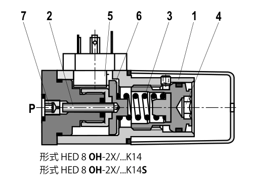
First establish the machine's acceptable pressure interval. If machining requires 90 bar to start but permission must be withdrawn below 85 bar, the assumed 90/80 bar pair would not meet the reset requirement. Compare the selected range's differential characteristics and measured switching points; another sensing arrangement may be needed.
The pressure tapping point changes what is confirmed
Assume an effective cylinder area of 50 cm². At 90 bar, ideal force is 45 kN. Return pressure, seal friction and mechanical transmission losses have not yet been deducted. Actual clamping force requires the complete force balance.
If the switch measures pump outlet pressure, a closed directional valve or blocked passage may allow the pump side to reach 90 bar while the cylinder has not developed the same pressure. A pressure-reached signal alone does not establish that the workpiece is clamped.
Analyse the pressure tapping point at the relevant actuator chamber and the required stroke or workpiece-position confirmation. Pressure and mechanical position provide different information.
Repeated switching requires checking both thresholds
Suppose a replenishment circuit stops at 90 bar and restarts at 80 bar. Pressure moving only between 84 and 88 bar would not repeatedly cross both thresholds in this assumed arrangement.
If each cycle reaches 92 bar and falls to 78 bar, it crosses both thresholds. Repeated switching then has a direct hydraulic explanation. Investigate replenishment capacity, normal consumption, leakage and pulsation. Adjusting the switch alone may simply change the cycle frequency.
| Observation | Compare | Practical interpretation |
|---|---|---|
| Consistent rising switch point but late reset | Both thresholds and process minimum | Differential may not suit the process |
| Input flickers while the gauge appears steady | Electrical signal, faster pressure record, wiring | A slow gauge can miss pulses; electrical faults remain possible |
| Pump pressure is reached but clamp force is low | Pump and clamp-chamber pressure, workpiece position | Tapping location or an intermediate passage may affect confirmation |
| A replacement switches at another pressure | Readings against the same gauge | An identical scale position does not replace calibration |
Match the contacts to the PLC input
The HED 8 provides microswitch contact functions for normally open or normally closed circuits. Use the specific connector diagram to identify terminals, then check the PLC input arrangement, voltage and permissible contact load. Correct wiring and correct control logic are separate checks.
If the program requires an active input after pressure builds, confirm the actual contact state during a pressure rise. A wrong contact selection can grant permission before pressure is established and remove it when pressure arrives.
Perform functional checks in an approved machine commissioning state with the existing interlocks retained. Applications needing continuous display, multiple independently adjustable thresholds or separate alarm and control outputs require a sensing device selected for those functions.
Record switching and reset pressure together
At normal oil temperature, use a suitable gauge and slowly increase and decrease pressure. Record the contact transitions and repeat several cycles to check consistency. Retain before-and-after readings so later changes can be compared with an actual baseline.
Where no recorder is available, two people can observe the existing gauge and input indication while operating and recording. This cannot quantify fast pulsation, but it can identify substantial setting errors, reversed contact logic and an unsuitable reset interval.
Select the HED 8 by adjustment range, the switching/reset interval needed by the process, and the hydraulic and electrical installation. A higher pressure rating alone does not make it a better match.