Rexroth 2FRE: Cylinder Speed under Changing Load
A cylinder that slows down when it meets the workpiece may be running out of pressure differential across its flow-control valve. The Rexroth 2FRE compensates for load changes, provided enough differential pressure remains available for regulation.
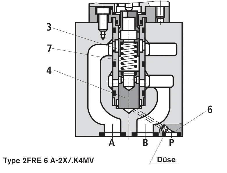
This discussion uses the 2FRE6, component series 2X, described in RE29188/02.07. A representative configuration is 2FRE6A-22/25QK4RV, with a 25 L/min progressive flow characteristic.
What the pressure compensator actually controls
With an ordinary fixed throttle opening, flow changes with pressure differential. A rising cylinder load raises the downstream pressure and reduces the differential available across the throttle. Cylinder speed then falls despite an unchanged opening.
The 2FRE combines a metering orifice with a pressure compensator. A proportional solenoid sets the metering opening, while an inductive transducer provides position feedback. The compensator adjusts the internal passage to maintain the differential required across the metering orifice.
This arrangement reduces the effect of load changes within its regulating range. Its feedback measures the metering-orifice position. A machine requiring closed-loop cylinder speed or position control still needs the appropriate actuator feedback.
A 15 L/min target needs a pressure margin
Assume an effective cylinder area of 50 cm² and a required speed of 50 mm/s. Required flow is 50 × 50 × 0.006 = 15 L/min. Use the full piston area for extension and the annular area for retraction.
Now assume 120 bar at the pump, 90 bar at the cylinder inlet and 10 bar lost through other series components. About 20 bar remains for the 2FRE. The cited catalog specifies a minimum differential of 6–10 bar. This example has pressure headroom for regulation, subject to checking the selected valve's actual characteristics.
If cylinder inlet pressure rises to 108 bar and the remaining circuit losses are 5 bar, only 7 bar remains across the flow-control valve. At a working point requiring 10 bar, compensation can no longer maintain the 15 L/min target.
Increasing the command may open the metering orifice further without restoring speed. Check loaded pump pressure, series pressure losses and available flow before changing the valve size or system settings.
| Assumed operating point | Pump | Cylinder inlet | Other losses | Available to 2FRE | Result |
|---|---|---|---|---|---|
| Normal load | 120 bar | 90 bar | 10 bar | 20 bar | Regulation headroom available |
| Higher load | 120 bar | 108 bar | 5 bar | 7 bar | Insufficient at a point requiring 10 bar |
These are pressure-budget examples, not machine measurements. Compare pressures during the same motion phase, at a similar oil temperature and an unchanged speed command.
The 25Q range covers the flow, but command is progressive
A 25 L/min range covers the theoretical 15 L/min requirement. It does not establish that a 60% command produces 15 L/min. Q denotes a progressive characteristic; use the relevant curve and the amplifier adjustment to establish the working command.
For a machine spending most of its cycle in fine feed and only a short period in rapid travel, compare low-speed resolution as well as maximum flow. Oversizing for rapid travel can concentrate normal operation into a small command range.
For 25Q, the cited data lists a maximum leakage of 22 cm³/min at zero command and 210 bar differential, measured at 41 mm²/s and 50°C. This conditional leakage rating also explains why closing a flow-control valve does not provide a dependable cylinder lock.
Where a vertical cylinder must hold a load, the load-holding circuit must provide that function. A zero speed command alone does not establish protection against a falling load.
An initial jump may involve the A-version closing function
Consider a feeder that retains its speed command while stopped and starts motion with a directional valve. The metering opening is already established before motion starts. The initial state of the compensator can therefore affect the first movement.
The 2FRE6A provides external closing of the compensator. In the OEM circuit, control pressure through port P holds it closed before the directional valve switches. It then moves into regulation, suppressing the startup jump. This function requires the corresponding pilot connection; installing an A valve alone does not reproduce the circuit.
If the machine instead starts from zero command and opens the valve through an amplifier ramp, inspect the ramp, feedback and actual startup response. An uneven start does not by itself establish that an A-version replacement is required.
The reverse check valve can bypass speed control
The R check-valve configuration permits free return flow from B to A. A feeder with controlled advance and a faster return may be operating exactly as that path intends. Restricting return speed requires suitable flow control for that direction.
The OEM Z4S6 rectifier sandwich plate can route flow through the regulating path in both directions. However, the catalog excludes combining this plate with the A external-closing configuration. It is not a universal accessory for every 2FRE6.
Compare speed, differential pressure and command
Without a flowmeter, stroke and travel time still provide a useful speed comparison. A 200 mm stroke taking 4 seconds initially and 5 seconds under load changes average speed from 50 to 40 mm/s. With the assumed 50 cm² area, average flow changes from 15 to 12 L/min.
Record pressure before and after the valve during that same motion and compare the command. A stable command with insufficient differential points first to the pressure budget. Adequate differential with a changing command directs attention to the control signal and amplifier.
Existing machine gauges and normal operating controls can support these observations. Pressure-line work, load-holding modifications and loaded commissioning require personnel qualified for those tasks.
The 2FRE suits electrically adjustable feed circuits that need reduced sensitivity to load changes. Establish required flow, check the pressure margin at the highest load, then address startup, reverse flow and load holding. A larger nominal flow range cannot compensate for a missing pressure margin.