MOOG D792 Three-Stage Servo Valve: High Flow and Pilot Configuration
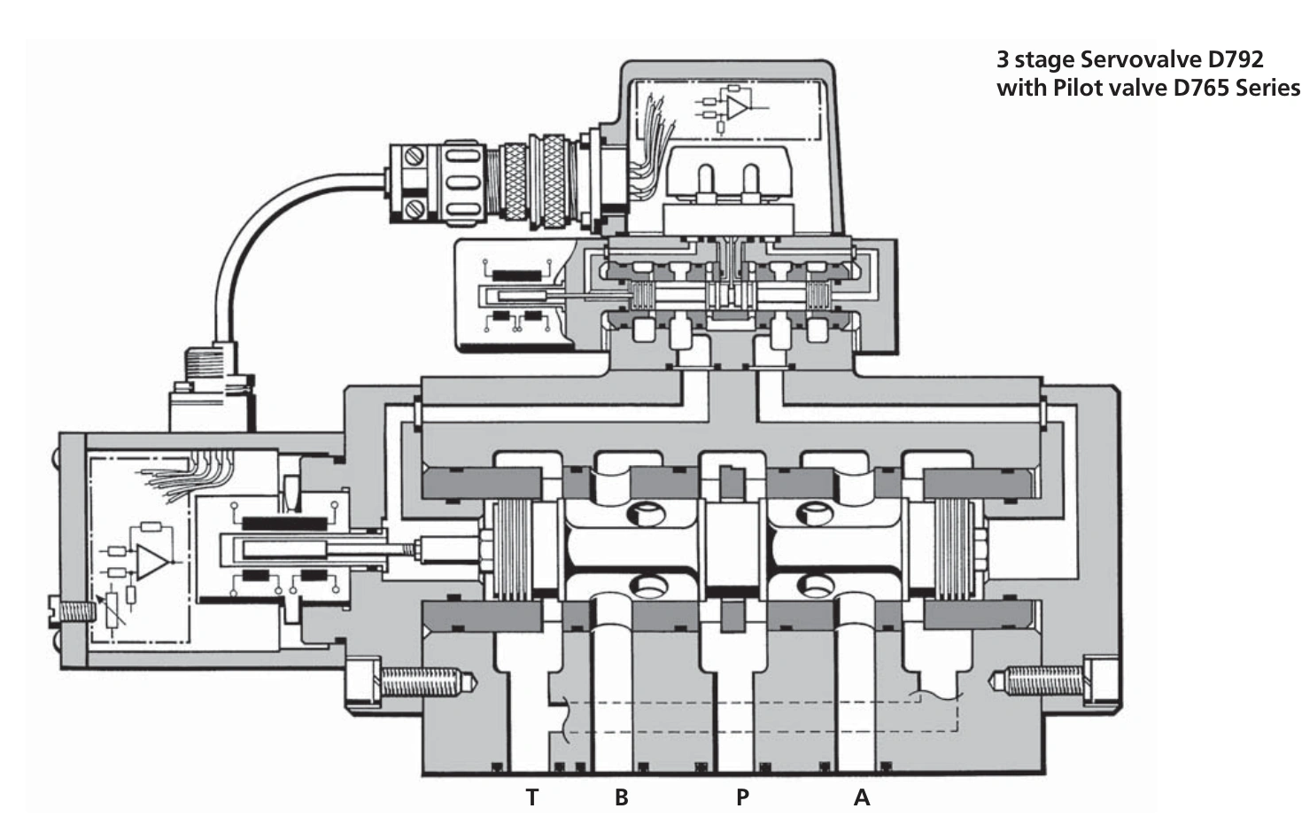
The MOOG D792 is a three-stage servo valve with rated flows of 400, 630, 800 and 1000 L/min. A two-stage pilot drives a large main spool. The main stage handles working flow, while position feedback controls main-spool opening.
The following covers D792 configurations with D761 and D765 pilots and uses a 600 L/min calculation example to explain flow sizing.
How Three Stages Control High Flow
The D792 pilot is itself a two-stage servo valve, available as a D761 or D765. It regulates differential pressure in the main-spool drive chambers. Main-spool movement changes the metering openings between P, A, B and T, controlling the equipment's working flow.
An LVDT measures actual main-spool position. The integrated amplifier compares feedback with the command and adjusts pilot output to make the main spool follow the command. The pilot provides hydraulic actuation; the main stage provides flow capacity.
The pilot changes the force available to move the main spool, so different pilots can give different response times at the same main-stage rating. The catalog range of 4–12 ms covers different configurations; it does not mean every D792 achieves 4 ms.
Rated Flows from 400 to 1000 L/min
| Catalogue parameter | D792 specification |
|---|---|
| Construction | Three stages, main spool in a bushing |
| Hydraulic arrangement | Four-way |
| Pilot valve | Two-stage D761 or D765 |
| Rated flow | 400, 630, 800, 1000 L/min |
| Rating condition | 35 bar per metering land; rated flow tolerance ±10% |
| Main-spool response, 0 to 100% stroke | 4–12 ms, depending on pilot valve |
| Mounting interface | MOOG-specific mounting pattern |
| Catalogue mass | 17 kg |
Response and the corresponding characteristic curves are measured at 210 bar pilot or operating pressure, 32 mm²/s viscosity and 40 °C oil temperature. The 4–12 ms range describes main-spool response under the catalogue conditions. Cylinder motion also depends on fluid compressibility, lines and load.
In a symmetrical four-way model, 35 bar per land corresponds to 70 bar across the inlet and return metering lands together. As load takes a larger share of supply pressure, less pressure drop remains for the valve and full-opening flow decreases.
A 630 L/min Version May Not Deliver a Required 600 L/min
Assume a symmetrical actuator needs 600 L/min and only 35 bar total pressure drop is available across the valve. At a fixed full opening, the square-root relation Q ≈ QN × √(35/70) gives the following estimates.
| Rated version | Estimated flow at 35 bar total drop | Assessment against 600 L/min |
|---|---|---|
| 400 L/min | Approximately 282.8 L/min | Insufficient |
| 630 L/min | Approximately 445.5 L/min | Insufficient |
| 800 L/min | Approximately 565.7 L/min | Insufficient |
| 1000 L/min | Approximately 707.1 L/min | Nominal calculated flow meets the requirement |
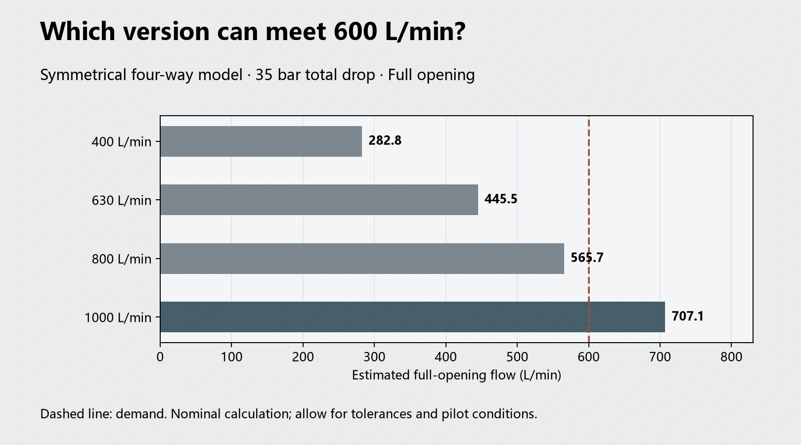
In this symmetrical-actuator calculation, the 630 and 800 versions fall short of 600 L/min, while the 1000 version delivers approximately 707.1 L/min. Applying the catalog negative rated-flow tolerance of 10% gives approximately 636.4 L/min for the 1000 version, reducing the remaining margin. Differential cylinders have unequal inlet and return flows, so this symmetrical result does not apply directly.
At 600 L/min and 35 bar total drop, throttling power is approximately 35 × 600 ÷ 600 = 35 kW. Even with sufficient flow, this energy becomes heat that the power unit and cooling system must handle.
Why a 30 bar Pilot Supply Can Still Be Insufficient
The catalogue requires pilot supply pressure to be at least 15 bar above pilot return pressure. This is a minimum differential. High flow combined with a high valve pressure drop can require greater pilot pressure to overcome flow forces.
For example, a 30 bar pilot supply and 20 bar pilot return give only a 10 bar differential, below the catalogue minimum. A 40 bar supply with the same return gives 20 bar, meeting that minimum condition. The pilot pressure needed to drive the main stage at the actual operating point must still be checked.
Internal pilot supply draws from the main circuit. Unloading the main pump or operating at low pressure also reduces pilot pressure. An external X configuration can use an independent pilot supply; external Y return separates pilot return from the main return line and reduces the influence of its backpressure.
For example, during rapid retraction, return backpressure rises from 5 to 20 bar while pilot supply remains at 30 bar. Available pilot differential falls from 25 to 10 bar, below the catalog minimum of 15 bar. Main-spool drive can therefore be affected even with adequate main-pump delivery.
Older ±15 V and Current 24 V Versions
MOOG provides separate product pages for MFB-pilot and EFB-pilot versions. Both involve a three-stage main valve, but their interfaces, control functions and return-pressure limits are not all identical. Electrical main-spool feedback does not establish that the pilot valve also uses EFB.
The D761/D765 catalogue currently linked from the official product page lists a 315 bar maximum at main-stage P, A and B with internal X, and 350 bar with external X. The current MFB product page gives a general P, A and B maximum of 350 bar. The external-pilot 350 bar limit therefore cannot be assigned to every internal-pilot version in the older catalog.
The older catalog includes ±15 V electronics, while current product pages list 24 V supply versions. Their power arrangements differ, so the original power wiring cannot simply be reused. The amplifier and wiring designations must match the replacement electronics.
D792 Does Not Use a Generic NG Interface
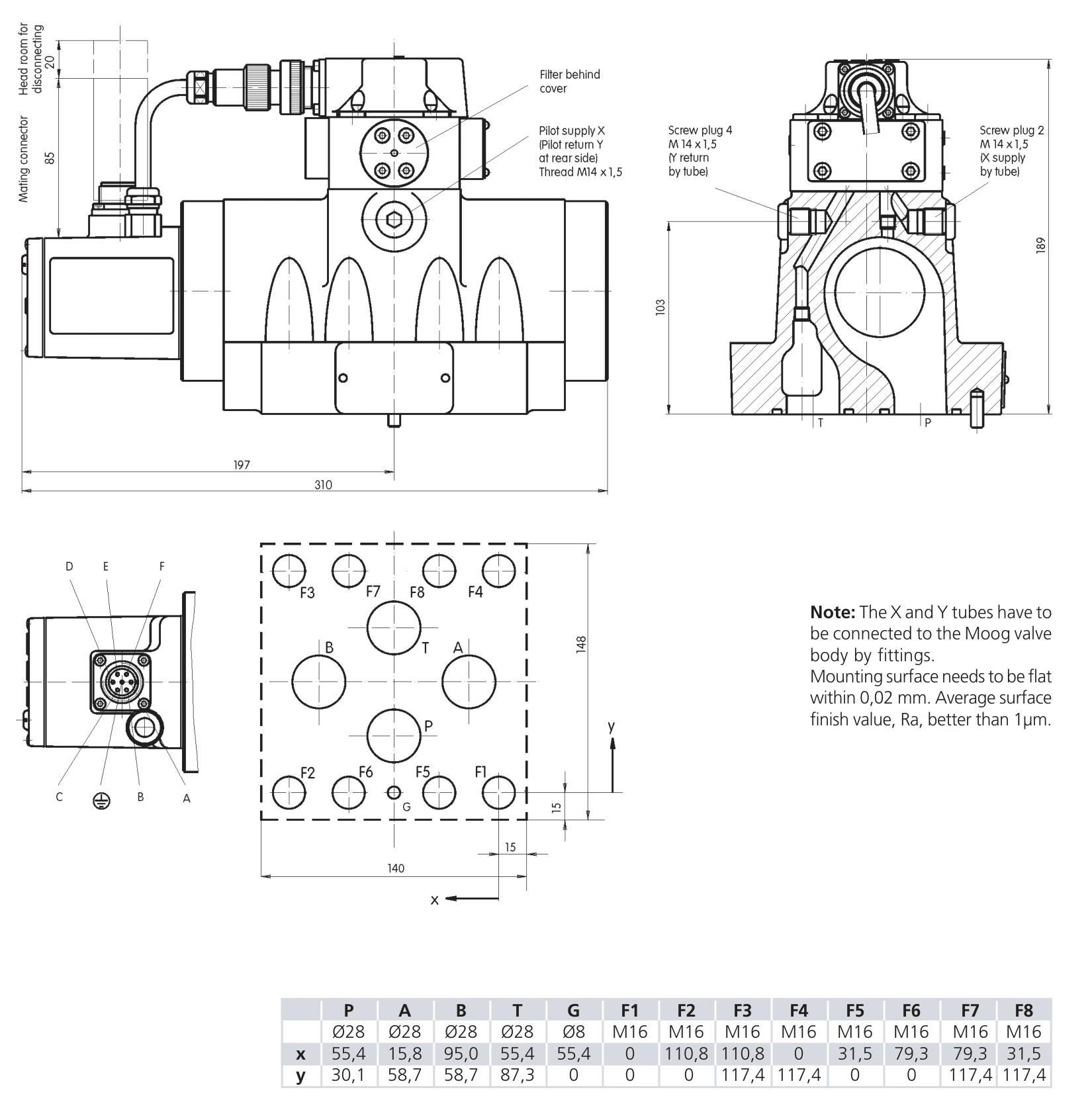
D792 uses a MOOG-specific mounting pattern. Manifold holes, ports and seal grooves must match the installation drawing; it is not a direct replacement on a generic NG interface. D761 and D765 upper assemblies also differ, which can change connector and maintenance clearance.
At high flow, manifold and line resistance consume part of the pressure-drop budget. The catalogue's flow-calculation guidance limits average velocity in P, A, B and T to 30 m/s. Check passage dimensions against the installation drawing and actual flow.
Selecting D792 for the 600 L/min Example
In the symmetrical calculation requiring 600 L/min at 35 bar total valve drop, the 630 version delivers approximately 445.5 L/min and the 800 version approximately 565.7 L/min. Both fall short. The 1000 version nominally delivers approximately 707.1 L/min, covering the demand.
However, this operating point generates approximately 35 kW of throttling heat. A pilot supply of 30 bar with 20 bar return also falls below the 15 bar minimum differential. Increasing the main-stage flow rating to 1000 L/min cannot fix that pilot-drive problem. Flow, pilot differential and cooling capacity are three concrete requirements for this example.