MOOG D791: Pilot Control of a High-Flow Main Stage
D791 places a two-stage pilot valve on a larger main stage, creating a three-stage assembly. The pilot positions the main spool while the main stage carries actuator flow. It suits duties combining substantial flow with fast control, such as hydraulic test mechanisms and rapidly controlled large cylinders.
This article follows the D791/2—EN/01.04 catalogue, with installation boundaries checked against the OEM instructions. Machine examples are illustrative.
From electrical command to main-spool position
Integrated electronics drives the pilot valve. The pilot develops differential pressure across the main-spool drive areas, moving the spool and changing the P, T, A and B flow openings.
A main-stage position transducer measures actual spool position. Electronics compares that signal with command and corrects pilot output. A relatively small pilot flow can therefore control a much larger main flow.
In a position-tracking test actuator, the valve loop positions the spool and the machine controller adjusts command from cylinder-position error. A faulty cylinder sensor can spoil tracking even when spool response is correct.
Select 100, 160 or 250 L/min at the available differential
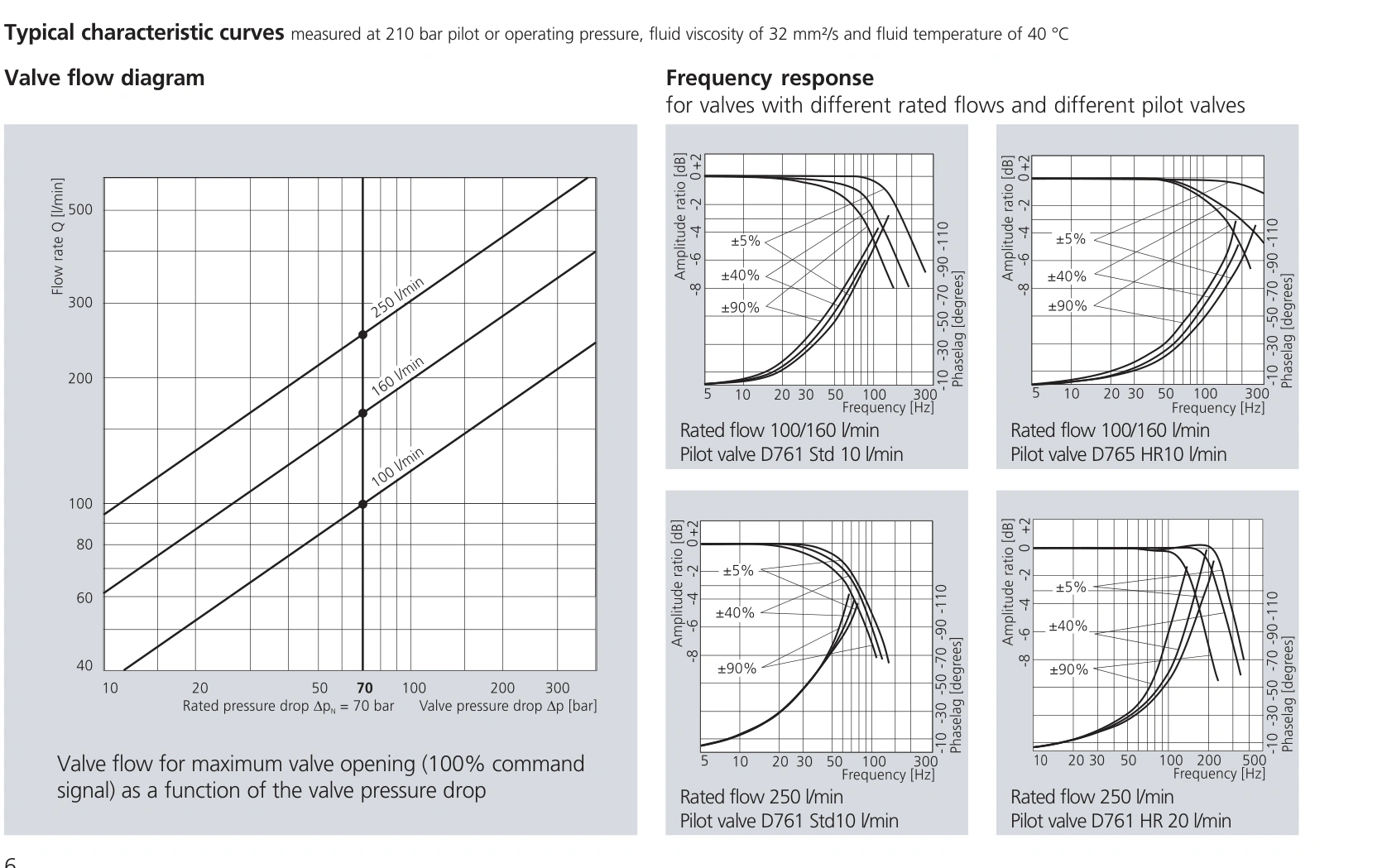
The referenced D791 grades are 100, 160 and 250 L/min at 35 bar per land, or 70 bar total across a standard four-way path.
A 100 cm² effective cylinder area moving at 200 mm/s needs 120 L/min. A 160 L/min grade has margin at rated differential. At 35 bar total valve drop, estimated flow at the same opening falls to about 113 L/min, below demand.
The 250 L/min grade gives an estimated 177 L/min under that differential and can proceed to further assessment. Pump delivery, port velocity, pilot pressure and heat remain relevant.
Insufficient pilot differential limits main-stage operation
The catalogue requires pilot pressure at least 15 bar above pilot return pressure. High flow and high valve drop may require more pilot pressure to overcome flow forces; 15 bar is a baseline condition, not a universal design setting.
For example, a 30 bar pilot inlet and 20 bar return provide only 10 bar differential, below that baseline. Slow response or incomplete spool travel warrants restoring pilot conditions before increasing command.
If operation deteriorates when another mechanism runs, record pilot inlet and return together. Supply loss and return-pressure rise reduce differential through different paths.
Pilot configuration affects dynamics
| Item | Referenced D791 data | Selection implication |
|---|---|---|
| Flow grades | 100, 160, 250 L/min | Assess demand and actual valve differential |
| Pilot options | D761 or D765 configurations | Compare their curves and supply requirements |
| Full-stroke response | 3–10 ms, configuration-dependent | Do not apply the fastest figure to every assembly |
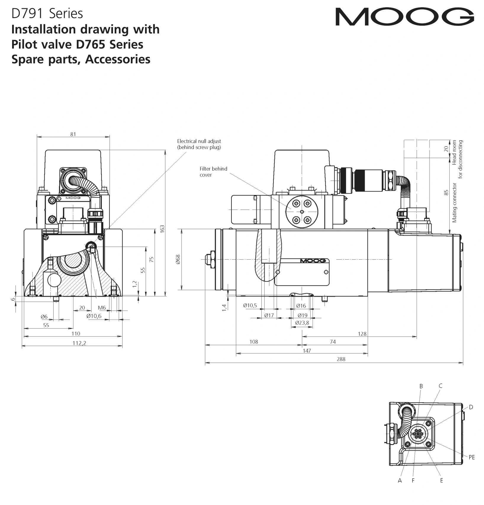
| Mounting | ISO 10372-06-05-0-92 with non-standard X/Y positions | Use the dedicated D791 drawing |
Machine response also depends on piping compliance, load inertia and controller settings. A faster pilot may not remove oscillation caused by long flexible hoses.
For replacement, identify both main-stage and pilot configuration. The catalogue explicitly notes that X and Y do not fully match the stated ISO pattern, making the dedicated installation drawing essential.
Select main-stage capacity, pilot configuration and effective pilot differential together. Then assess whether the complete hydraulic and control system can use the available valve dynamics.