HYDAC VD, VM and VR Clogging Indicators Compared
VD and VM detect differential pressure across a filter element. VR detects pressure at a return-line measuring point relative to atmosphere. All can prompt a filtration-system check, but their readings have different meanings.
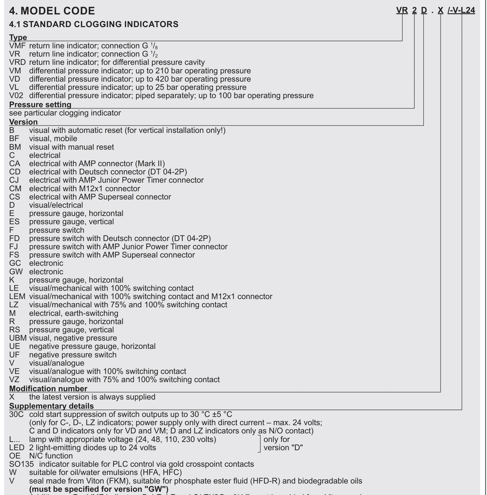
This article uses HYDAC document E7.050.15/11.16 for the product types listed on our website. Confirm response setting, contacts and pressure rating against the complete ordering code.
VD and VM are both differential-pressure types
The referenced standard VD family is rated up to 420 bar operating pressure and VM up to 210 bar. Operating-pressure capacity is separate from the differential pressure that triggers an indication.
In VD5D.0/-L24, 5 identifies a 5 bar response differential. It does not limit installation to a 5 bar system. D identifies combined visual and electrical indication; L24 denotes a 24 V indicator-lamp arrangement, not a continuous 4–20 mA measurement output.
| Type | Measured quantity | Main check |
|---|---|---|
| VD | Differential pressure across the element | Operating rating, response setting and indication |
| VM | Differential pressure across the element | Its pressure rating differs from VD |
| VR | Pressure at the return-line measuring point | Filter restriction plus downstream backpressure |
| VMF | Return-line type | Complete code and connection; not the same as VM |
The same 180 bar inlet pressure can give different results
Consider illustrative readings of 180 bar before an element and 178 bar after it. Differential pressure is 2 bar. A 5 bar indicator does not trigger merely because upstream pressure is 180 bar.
If upstream pressure remains 180 bar while downstream pressure falls to 174 bar, differential pressure becomes 6 bar. That exceeds the nominal 5 bar response setting, subject to response tolerance and actual switch operation.
A single upstream gauge cannot establish filter differential pressure. Record oil temperature, operating flow and visual indication, then have maintenance personnel verify appropriate measuring points with suitable instruments.
A VR alarm can include return-line backpressure
Suppose a VR point reads 2.5 bar while downstream return backpressure is 1.8 bar. The filter accounts for only about 0.7 bar. A 2 bar VR response may therefore occur even though most of the measured pressure comes from the downstream return path.
Check return-line restrictions, tank return conditions and downstream components. Replacing the element may leave the alarm unchanged if backpressure is the cause. Permitted operating pressure also varies between VR indication variants; do not apply one variant's rating to the whole family.
An alarm that clears after warm-up
Cold, viscous oil can increase filtration pressure loss. If an alarm clears as oil warms, repeat the assessment at the specified temperature and comparable flow before judging element condition.
If it persists at normal temperature and flow, check the element, indicator passages and response. Some variants offer cold-start suppression, but it must be identified by the applicable option code; it is not standard on every D version.
If visual indication and PLC alarm disagree, check reset behaviour, contact definition and wiring. Suffixes such as B and BM distinguish automatic and manual reset behaviour, which affects whether an earlier alarm remains visible.
For VD and VM, assess differential pressure. For VR, include return backpressure. Match measurement type, response setting, operating rating, reset function and electrical arrangement together.