3 vs 10 Micron Filters: Why Differential Pressure Rises
A 3 μm replacement may alarm where a 10 μm element did not. Causes can include increased clean resistance, cold oil, peak return flow or contamination loading. Compare differential at the same temperature and duty before drawing a conclusion.
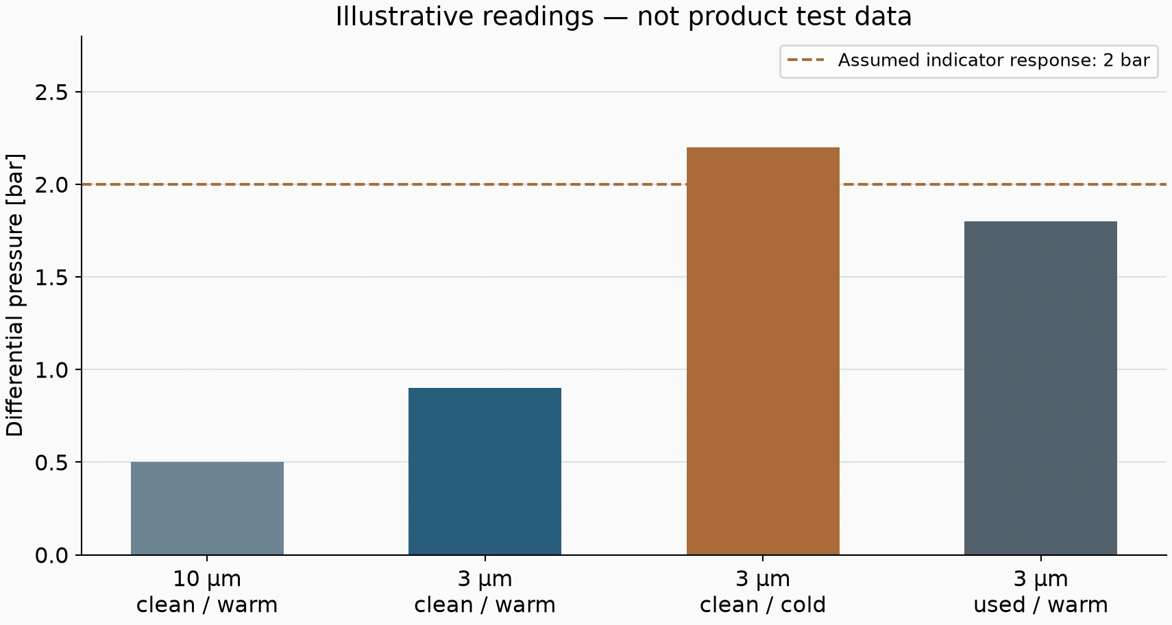
The following readings are illustrative, not measured HYDAC product curves.
Filtration grade and differential describe different properties
Grade describes particle separation. Differential describes resistance across the current filtration assembly. Finer media can increase clean pressure loss where construction and area are comparable, but 3 and 10 μm labels do not establish a fixed resistance ratio.
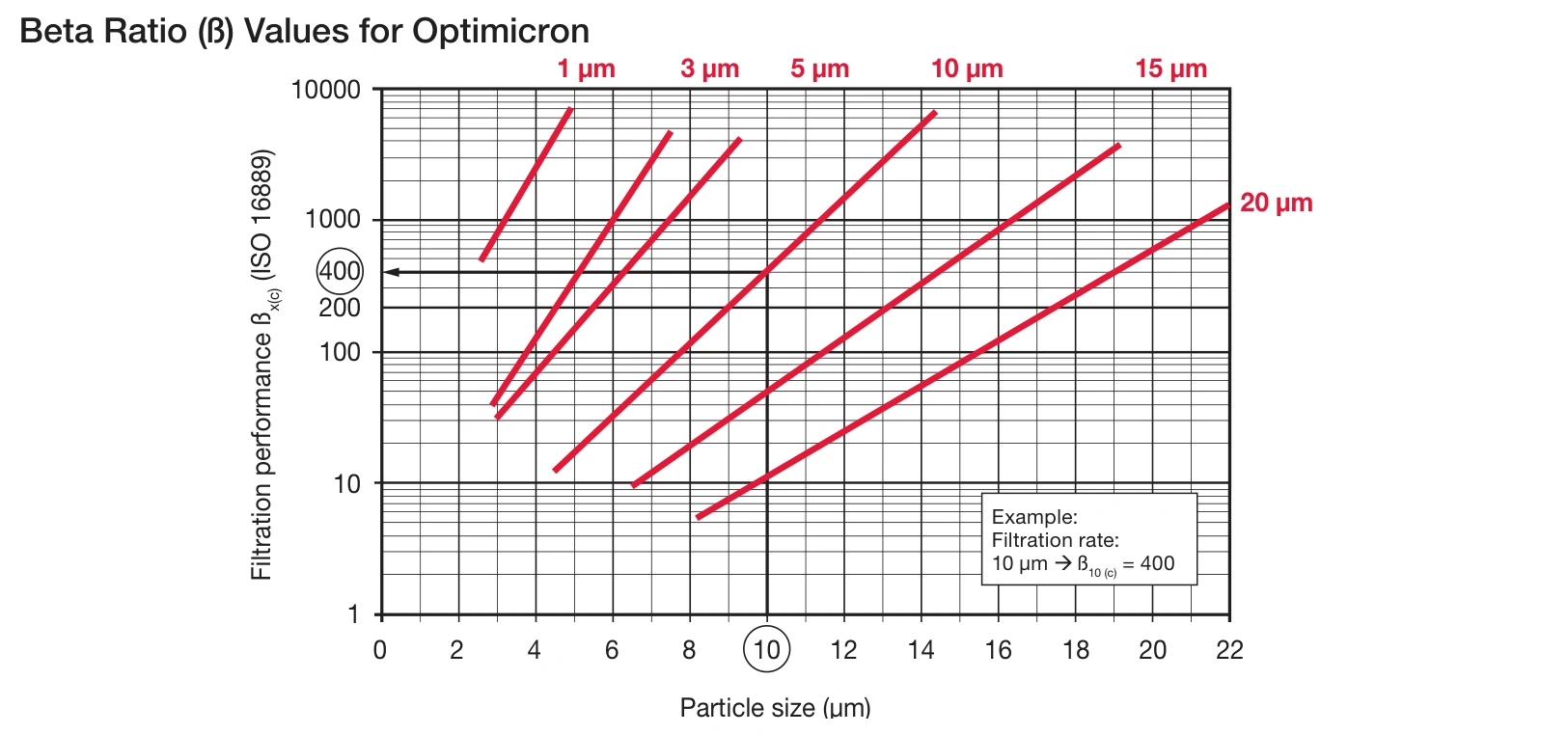
Different products may also have different media area and efficiency. Compare their beta curves and assembly pressure-loss data.
Compare cold readings with a warm clean baseline
Suppose the old 10 μm arrangement gives 0.5 bar differential at normal temperature and a fixed flow. A clean 3 μm replacement gives 0.9 bar under the same conditions. That difference can be clean resistance rather than blockage.
If the new arrangement reaches 2.2 bar cold and returns to 0.9 bar warm, an illustrative 2 bar indicator explains the cold-only alarm. The 2 bar value is not a universal setting.
If its warm reading later rises from 0.9 to 1.8 bar at the same duty, investigate loading, flow and element condition against the original clean baseline.
Alarms during rapid return call for flow checks
Cylinder retraction, simultaneous returns and accumulator discharge can create flow peaks. A finer element may leave less differential margin for them.
If feeding motion is normal but retraction alarms, calculate cap/rod area ratio and return flow. Unchanged pump delivery does not establish unchanged maximum return flow.
Where peaks exceed assembly capability, assess area, size or circuit design. Raising the alarm threshold does not restore filtration flow capacity.
Persistent warm differential needs a broader check
High warm differential soon after replacement warrants checks of contamination, model, installation and passages. Finer media may capture material previously circulating through the system.
For a return-pressure indicator, also check downstream backpressure. Pressure at a return point is not necessarily differential across the element.
| Condition | Assessment |
|---|---|
| High warm differential with a clean element | Larger area or suitable assembly |
| Cold-only alarm | Lowest operating temperature and viscosity |
| Alarm during fast or simultaneous return | Peak flow |
| Rising warm baseline | Contamination load and element condition |
| Frequent bypass after finer replacement | Grade, area and peak-flow compatibility |
A designer may assess offline fine filtration where useful, while retaining the required immediate protection of critical components.
Establish the cleanliness target before choosing 3 μm
For a lubrication circuit already meeting component cleanliness requirements, assess finer filtration against contamination analysis. Frequent bypass after a finer replacement may undermine the intended improvement.
A machine adding more particle-sensitive control components may genuinely need better filtration. Compare media grade with larger elements, greater area, suitable offline filtration and source control.
Open tank access, maintenance debris and contaminated filling can continuously add particles. Filtered filling, sound seals and clean maintenance practices can reduce loading as effectively as changing the media strategy.
Keep the first clean-element readings as a baseline
At specified oil temperature, repeatable flow and representative motions, record clean differential. Also retain cold-start and maximum-return readings for later comparison.
A retraction peak rising from 1.6 to 1.7 bar differs from one rising from 0.6 to 1.7 bar. The final 1.7 bar reading alone does not describe the change in condition.
Record full element code, temperature, operating step and replacement time. Where instruments are limited, use existing indicators and trends first; qualified personnel can add measurements under procedure.
Assess warning and bypass together
Warning should provide maintenance notice before the applicable bypass action. A higher clean differential calls for assembly reassessment rather than moving warning above bypass.
A no-bypass arrangement requires careful cold and peak-flow checks. A bypass-equipped arrangement also requires assessment of the oil path and downstream protection during bypass.
A finer grade has value when the system reaches its required cleanliness and the assembly can still handle minimum-temperature viscosity and maximum return flow. Assess both requirements together.