HYDAC KHB vs KHNVN: Selecting Isolation Ball Valves
A 200 bar main supply and a 6 bar cooling branch need different valve assessments. Main-line pressure capability and flow passage both matter. Low-pressure branches also require suitable bore, temperature and connection sealing.
The examples use HYDAC KHB/KHM 06.22 and KHNVN EN5.507.12/11.23 separately. Actual maximum installation pressure must include applicable transient and abnormal conditions.
A 200 bar, 30 L/min main line needs a suitable KHB configuration
Assume the valve isolates a power unit from a valve bank at 30 L/min and 200 bar. The cited KHNVN specifications, with a maximum of PN50, do not meet this pressure requirement.
The KHB BSP table lists G3/4, DN20, a 20 mm bore and PN420. This permits further material, temperature and pressure-loss assessment for the example; the actual assembly must meet the complete maximum-pressure requirement.
The listed KHB-G1/4-1112-03X-A-SW09 has a smaller passage to consider. The KHB-G1/4 family table gives DN6 and an 8 mm bore. A high pressure rating does not remove the flow requirement.
At 30 L/min, mean velocity through an 8 mm circular bore is approximately 9.9 m/s, compared with 1.6 m/s through 20 mm. These are not valve pressure-drop values, but they establish different flow conditions. Check the combined permitted loss through valve, fittings and lines.
A 6 bar maximum, 40 L/min cooling branch: compare DN20 with DN10
Assume an independent cooling branch has a verified design maximum of 6 bar, including its pressure-control and abnormal-condition protection, at 40 L/min. Suitable low-pressure valves can be evaluated within medium, temperature and connection limits.
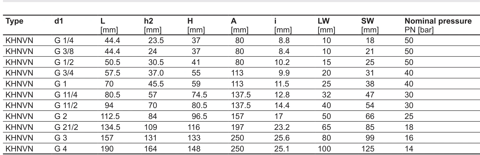
The cited KHNVN table lists G3/4 at LW20 mm and PN40, while G3/8 is LW10 mm and PN50. The website has KHNVN DN20 and DN10 entries; confirm the complete connection configuration when ordering.
At 40 L/min, mean velocity is approximately 2.1 m/s through 20 mm and 8.5 m/s through 10 mm. Evaluate DN20 connection and pressure loss for this duty rather than choosing DN10 because PN50 exceeds PN40.
The 6 bar figure must be the verified installation maximum. If it is only the normal gauge reading and the upstream pump can raise pressure against a closed valve, use that possible closed-valve pressure in selection.
Larger KHNVN passages have their own PN ratings
The website also lists KHNVN DN32 and DN40. In this manual, G1¼/LW32 and G1½/LW40 are both PN30. PN50 does not apply to every size.
| Installation duty | Selection conclusion | Remaining checks |
|---|---|---|
| 200 bar main line, 30 L/min | Exclude the cited KHNVN range; assess suitable KHB | Maximum pressure, materials, temperature and losses |
| Verified 6 bar cooling branch, 40 L/min | DN20 offers a larger passage than DN10 | Connections, permitted loss and temperature |
| DN32 or DN40 low-pressure line | Use the corresponding PN30 reference | Actual maximum pressure and dimensions |
| Downstream accumulator or loaded cylinder | Closing a valve does not complete depressurisation | Isolation, locking, release and pressure confirmation |
Downstream stored pressure remains after closing
If a downstream accumulator contains 100 bar when isolation closes, that pressure remains in the accumulator and trapped line. Closing the supply does not discharge stored pressure, even without an external leak.
The maintenance arrangement must define pressure release, confirmation and prevention of inadvertent opening. Handle position indicates operation only. Required locking accessories, measuring points and release devices must be provided.
Depressurising a gravity-loaded cylinder also affects support. Retain the specified mechanical support or holding measures; loosening a fitting is not a pressure-confirmation method.
Materials and fitting geometry must also match
This KHNVN version specifies nickel-plated brass housing, chrome-plated brass ball/spindle and PTFE seals. KHB offers different combinations. Its final 2 in 1112 identifies NBR in the cited code; do not assign every standard 1114 temperature condition to 1112.
The KHNVN manual restricts the relevant GE screw-in fittings because of thread depth and EO sealing geometry. Equal thread size still requires compatible sealing construction.
Provide installation duty, maximum pressure and flow, temperature/medium, existing fitting photographs and handle clearance when ordering. Check the replacement's complete model, pressure conditions, passage and sealing, then verify leakage and losses under the machine procedure.
High-pressure supply requires both pressure and flow capability. A low-pressure high-flow branch should not sacrifice passage size solely for a higher PN number. Isolation suitability depends on the installation, while maintenance also requires locking, pressure release and confirmation.