HYDAC 0160 R 003 ON: Return Filter Selection
0160 R 003 ON is a return-line element. Select it for peak return flow, permissible differential, bypass configuration and the machine's cleanliness target.
This article uses HYDAC part number 1262955. B1, B6, KB and other suffix variants require their own configuration checks.
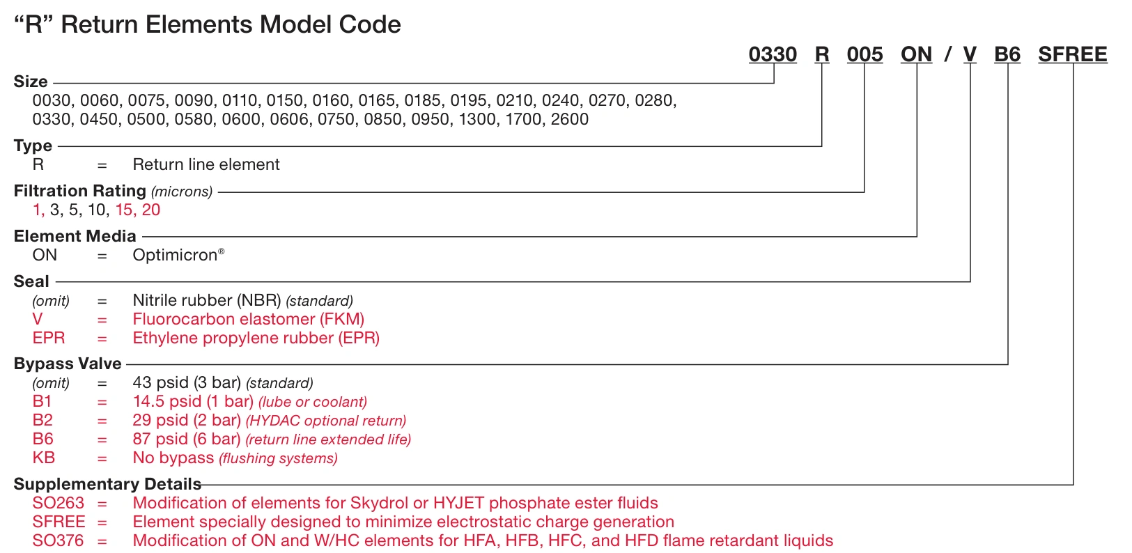
Model breakdown
| Field | Meaning | Check |
|---|---|---|
| 0160 | Size designation | Not a fixed 160 L/min flow rating |
| R | Return element | Housing and connection compatibility |
| 003 | 3 μm filtration grade | Efficiency curve and cleanliness requirement |
| ON | Optimicron media | Product and fluid compatibility |
The OEM page lists 73 mm outside diameter, 145 mm length, 34 mm inside diameter, NBR seals and outside-to-inside flow. Match end caps, seal positions and bypass arrangement as well as dimensions.
A 3 bar bypass differs from a 20 bar collapse rating
Part 1262955 lists a standard 3 bar bypass setting and 20 bar collapse rating. The former concerns bypass opening; the latter concerns structural differential-pressure capability. It is not a continuous operating target for a blocked element.
If differential approaches bypass operation, some flow may avoid the media. Continued machine movement does not establish that all return oil is still being filtered through the element.
Check bypass setting, clogging-indicator response and housing operating-pressure rating separately. A different suffix may change how alarm and bypass functions relate.
Return flow can exceed pump delivery
Consider a differential cylinder with a 100 cm² cap area and 60 cm² effective rod-side area. During retraction, 30 L/min entering the rod side produces approximately 50 L/min leaving the cap side.
A filter in that return path must accommodate this flow and other simultaneous returns. An alarm during rapid retraction warrants checking the return peak before blaming the element.
Size code 0160 does not replace pressure-loss assessment. Use the actual assembly's data for viscosity, media, flow and contamination conditions.
Select the grade for the cleanliness target
A 3 μm grade is a candidate where fine-particle control is needed, but selection depends on component ISO 4406 requirements, contamination loading and filtration capacity. Assess cold differential and peak flow alongside filtration performance.
Efficiency is expressed through quantities such as βx(c), where x identifies the evaluated particle size. A beta ratio of 1000 means 99.9% count removal for the corresponding particle range in the test. It does not describe removal of every contaminant throughout a machine, and the 003 code alone should not be used to invent the beta subscript.
| Observation | Check first |
|---|---|
| Alarm during fast retraction | Area-ratio return peak |
| Cold alarm clearing warm | Viscosity and clean-element pressure loss |
| Persistent high differential warm | Loading, flow, passages and indicator |
| Changed alarm behaviour after replacement | Full suffix, bypass and indicator settings |
Select the indicator for the filter assembly first
The housing's sensing connection and internal passages determine indicator compatibility. A differential type needs pressures from both sides of the element; a return-pressure type senses one measuring point. Matching threads alone do not establish interchangeability.
HYDAC VD and VM are differential-pressure types, while VR is a return-pressure type. Retain the specified sensing arrangement: assess return backpressure for an assembly designed for VR, or select a compatible differential type for a differential connection. Do not modify the housing or its passages to fit an arbitrary indicator.
Place the warning between normal differential and bypass operation
For the standard 3 bar bypass discussed here, warning should precede bypass operation while allowing normal clean-element differential. Include indicator and bypass tolerances, cold viscosity and return-flow peaks.
Consider a hypothetical assembly with 0.6 bar clean warm differential and a 1.1 bar maximum normal peak. A design using a 2 bar indicator and 3 bar bypass is viable only if the assembly permits it and tolerance margins remain adequate.
If a clean element already reaches 1.9 bar in normal motion, 2 bar warning has little margin. Reassess flow, filtration area and viscosity rather than simply raising the threshold. Warning after bypass opening provides no advance maintenance notice.
Return backpressure changes pressure-type readings
With 0.6 bar element differential and 1 bar downstream backpressure, upstream gauge pressure is approximately 1.6 bar. A pressure type sees the latter; a differential type senses 0.6 bar. Setpoints must suit the selected measurement.
The element code alone does not establish housing connection, indicator operating-pressure rating or original assembly setting. Obtain the housing model and circuit arrangement.
Specify electrical output and reset behaviour
| Item | Selection detail |
|---|---|
| Measurement | Differential or return pressure, matching the assembly |
| Response | Maximum normal differential, tolerances and bypass margin |
| Pressure rating | Indicator body's permissible operating pressure |
| Output | Visual, electrical or combined; normally open/closed contacts |
| Wiring | Contact voltage/current ratings, connector and PLC logic |
| Reset and temperature | Automatic/manual reset and applicable cold-start option |
Choose a compatible electrical or combined type where a PLC must prompt maintenance. A visual indicator needs an accessible viewing position. A 24 V lamp does not establish continuous 4–20 mA differential output.
Use cold-start suppression or program delay only as designed. Neither makes excessive cold differential acceptable or justifies hiding persistent blockage or bypass risk.
Size for the return duty. Keep the standard 3 bar bypass separate from the 20 bar collapse rating, then assess peak flow and cold differential before choosing the 3 μm grade.